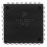
MC9S12D64CPVE Freescale Semiconductor, MC9S12D64CPVE Datasheet - Page 109

MC9S12D64CPVE
Manufacturer Part Number
MC9S12D64CPVE
Description
IC MCU 64K FLASH 25MHZ 112LQFP
Manufacturer
Freescale Semiconductor
Series
HCS12r
Specifications of MC9S12D64CPVE
Core Processor
HCS12
Core Size
16-Bit
Speed
25MHz
Connectivity
CAN, I²C, SCI, SPI
Peripherals
PWM, WDT
Number Of I /o
91
Program Memory Size
64KB (64K x 8)
Program Memory Type
FLASH
Eeprom Size
1K x 8
Ram Size
4K x 8
Voltage - Supply (vcc/vdd)
2.35 V ~ 5.25 V
Data Converters
A/D 16x10b
Oscillator Type
Internal
Operating Temperature
-40°C ~ 85°C
Package / Case
112-LQFP
Processor Series
S12D
Core
HCS12
Data Bus Width
16 bit
Data Ram Size
4 KB
Interface Type
CAN/I2C/SCI/SPI
Maximum Clock Frequency
25 MHz
Number Of Programmable I/os
49
Number Of Timers
8
Maximum Operating Temperature
+ 85 C
Mounting Style
SMD/SMT
3rd Party Development Tools
EWHCS12
Development Tools By Supplier
M68KIT912DP256
Minimum Operating Temperature
- 40 C
On-chip Adc
2 (8-ch x 10-bit)
Lead Free Status / RoHS Status
Lead free / RoHS Compliant
Available stocks
Company
Part Number
Manufacturer
Quantity
Price
Company:
Part Number:
MC9S12D64CPVE
Manufacturer:
Freescale Semiconductor
Quantity:
10 000
Part Number:
MC9S12D64CPVE
Manufacturer:
FREESCALE
Quantity:
20 000
A.5.3 Phase Locked Loop
The oscillator provides the reference clock for the PLL. The PLL´s Voltage Controlled Oscillator (VCO)
is also the system clock source in self clock mode.
A.5.3.1 XFC Component Selection
This section describes the selection of the XFC components to achieve a good filter characteristics.
The following procedure can be used to calculate the resistance and capacitance values using typical
values for K
The grey boxes show the calculation for f
for f
The VCO Gain at the desired VCO frequency is approximated by:
NOTES:
1. Depending on the crystal a damping series resistor might be necessary
2. f
3. Maximum value is for extreme cases using high Q, low frequency crystals
4. Only valid if Pierce oscillator/external clock mode is selected
osc
OSC
= 4MHz, C = 22pF.
= 4MHz and a 25MHz bus clock.
1
, f
1
and i
f
osc
K
V
ch
from Table A-16.
=
K
refdv+1
Figure A-2 Basic PLL functional diagram
1
1
e
---------------------- -
f
K
1
1
f
–
ref
VDDPLL
f
1V
VCO
vco
=
= 50MHz and f
–
100
f
cmp
C
C
p
Loop Divider
s
e
Detector
----------------------- -
Phase
60 50
synr+1
–
K
100
ref
1
–
R
MC9S12DJ64 Device User Guide — V01.20
= 1MHz. E.g., these frequencies are used
= -90.48MHz/V
XFC Pin
1
2
VCO
K
V
f
vco
109


