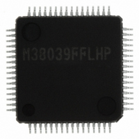
M38039FFLHP#U0 Renesas Electronics America, M38039FFLHP#U0 Datasheet - Page 28

M38039FFLHP#U0
Manufacturer Part Number
M38039FFLHP#U0
Description
IC 3803 MCU FLASH 64LQFP
Manufacturer
Renesas Electronics America
Series
740/38000r
Datasheet
1.M38039FFLHPU0.pdf
(121 pages)
Specifications of M38039FFLHP#U0
Core Processor
740
Core Size
8-Bit
Speed
16.8MHz
Connectivity
SIO, UART/USART
Peripherals
PWM, WDT
Number Of I /o
56
Program Memory Size
60KB (60K x 8)
Program Memory Type
FLASH
Ram Size
2K x 8
Voltage - Supply (vcc/vdd)
2.7 V ~ 5.5 V
Data Converters
A/D 16x10b; D/A 2x8b
Oscillator Type
Internal
Operating Temperature
-20°C ~ 85°C
Package / Case
64-LQFP
Lead Free Status / RoHS Status
Lead free / RoHS Compliant
Eeprom Size
-
Available stocks
Company
Part Number
Manufacturer
Quantity
Price
3803 Group (Spec.L)
Rev.1.01
REJ03B0212-0101
Fig 20. Interrupt control diagram
• Interrupt Disable Flag
The interrupt disable flag is assigned to bit 2 of the processor
status register. This flag controls the acceptance of all interrupt
requests except for the BRK instruction. When this flag is set to
“1”, the acceptance of interrupt requests is disabled. When it is
set to “0”, acceptance of interrupt requests is enabled. This flag is
set to “1” with the SET instruction and set to “0” with the CLI
instruction.
When an interrupt request is accepted, the contents of the
processor status register are pushed onto the stack while the
interrupt disable flag remaines set to “0”. Subsequently, this flag
is automatically set to “1” and multiple interrupts are disabled.
To use multiple interrupts, set this flag to “0” with the CLI
instruction within the interrupt processing routine.
The contents of the processor status register are popped off the
stack with the RTI instruction.
• Interrupt Request Bits
Once an interrupt request is generated, the corresponding
interrupt request bit is set to “1” and remaines “1” until the
request is accepted. When the request is accepted, this bit is
automatically set to “0”.
Each interrupt request bit can be set to “0”, but cannot be set to
“1”, by software.
• Interrupt Enable Bits
The interrupt enable bits control the acceptance of the
corresponding interrupt requests. When an interrupt enable bit is
set to “0”, the acceptance of the corresponding interrupt request
is disabled. If an interrupt request occurs in this condition, the
corresponding interrupt request bit is set to “1”, but the interrupt
request is not accepted. When an interrupt enable bit is set to “1”,
acceptance of the corresponding interrupt request is enabled.
Each interrupt enable bit can be set to “0” or “1” by software.
The interrupt enable bit for an unused interrupt should be set to
“0”.
Jan 25, 2008
Interrupt request bit
Interrupt enable bit
Interrupt disable flag (I)
Page 26 of 117
BRK instruction
Reset
• Interrupt Source Selection
Any of the following combinations can be selected by the
interrupt source selection register (0039
• External Interrupt Pin Selection
For external interrupts INT
switch bit in the interrupt edge selection register (bit 6 of address
003A
INT
1. INT
2. CNTR
3. Serial I/O2 or timer Z
4. INT
5. A/D conversion or serial I/O3 transmission
01
16
and INT
) can be used to select INT
0
4
or timer Z
or CNTR
1
or Serial I/O3 reception
41
pin input.
2
0
and INT
Interrupt request
00
4
, the INT
16
and INT
).
0
, INT
40
pin input or
4
interrupt


