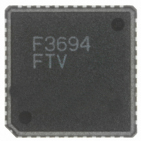
HD64F3694FTV Renesas Electronics America, HD64F3694FTV Datasheet - Page 294

HD64F3694FTV
Manufacturer Part Number
HD64F3694FTV
Description
IC H8/3694F MCU FLASH 48-QFN
Manufacturer
Renesas Electronics America
Series
H8® H8/300H Tinyr
Datasheet
1.HD64F3694GFYV.pdf
(452 pages)
Specifications of HD64F3694FTV
Core Processor
H8/300H
Core Size
16-Bit
Speed
20MHz
Connectivity
I²C, SCI
Peripherals
PWM, WDT
Number Of I /o
29
Program Memory Size
32KB (32K x 8)
Program Memory Type
FLASH
Ram Size
2K x 8
Voltage - Supply (vcc/vdd)
3 V ~ 5.5 V
Data Converters
A/D 8x10b
Oscillator Type
Internal
Operating Temperature
-20°C ~ 75°C
Package / Case
48-QFN
For Use With
R0K436079S000BE - KIT DEV FOR H8/36079 W/COMPILER
Lead Free Status / RoHS Status
Lead free / RoHS Compliant
Eeprom Size
-
- Current page: 294 of 452
- Download datasheet (3Mb)
Section 15 I
15.7
15.7.1
In master mode, when the start/stop conditions are issued (retransmitted) at the specific timing
under the following condition 1 or 2, such conditions may not be output successfully. To avoid
this, issue (retransmit) the start/stop conditions after the fall of the ninth clock is confirmed. Check
the SCLO bit in the I
1. When the rising of SCL falls behind the time specified in section 17.6, Bit Synchronous
2. When the bit synchronous circuit is activated by extending the low period of eighth and ninth
15.7.2
If the WAIT bit is set to 1, and the SCL signal is driven low for two or more transfer clocks by the
slave device at the eighth and ninth clocks, the high period of ninth clock may be shortened. To
avoid this, set the WAIT bit in ICMR to 0.
Rev.5.00 Nov. 02, 2005 Page 264 of 418
REJ09B0028-0500
Circuit, by the load of the SCL bus (load capacitance or pull-up resistance)
clocks, that is driven by the slave device
Usage Notes
Issue (Retransmission) of Start/Stop Conditions
WAIT Setting in I
2
C Bus Interface 2 (IIC2)
2
C control register 2 (IICR2) to confirm the fall of the ninth clock.
2
C Bus Mode Register (ICMR)
Related parts for HD64F3694FTV
Image
Part Number
Description
Manufacturer
Datasheet
Request
R

Part Number:
Description:
KIT STARTER FOR M16C/29
Manufacturer:
Renesas Electronics America
Datasheet:

Part Number:
Description:
KIT STARTER FOR R8C/2D
Manufacturer:
Renesas Electronics America
Datasheet:

Part Number:
Description:
R0K33062P STARTER KIT
Manufacturer:
Renesas Electronics America
Datasheet:

Part Number:
Description:
KIT STARTER FOR R8C/23 E8A
Manufacturer:
Renesas Electronics America
Datasheet:

Part Number:
Description:
KIT STARTER FOR R8C/25
Manufacturer:
Renesas Electronics America
Datasheet:

Part Number:
Description:
KIT STARTER H8S2456 SHARPE DSPLY
Manufacturer:
Renesas Electronics America
Datasheet:

Part Number:
Description:
KIT STARTER FOR R8C38C
Manufacturer:
Renesas Electronics America
Datasheet:

Part Number:
Description:
KIT STARTER FOR R8C35C
Manufacturer:
Renesas Electronics America
Datasheet:

Part Number:
Description:
KIT STARTER FOR R8CL3AC+LCD APPS
Manufacturer:
Renesas Electronics America
Datasheet:

Part Number:
Description:
KIT STARTER FOR RX610
Manufacturer:
Renesas Electronics America
Datasheet:

Part Number:
Description:
KIT STARTER FOR R32C/118
Manufacturer:
Renesas Electronics America
Datasheet:

Part Number:
Description:
KIT DEV RSK-R8C/26-29
Manufacturer:
Renesas Electronics America
Datasheet:

Part Number:
Description:
KIT STARTER FOR SH7124
Manufacturer:
Renesas Electronics America
Datasheet:

Part Number:
Description:
KIT STARTER FOR H8SX/1622
Manufacturer:
Renesas Electronics America
Datasheet:


