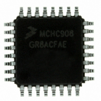
MCHC908GR8ACFAE Freescale Semiconductor, MCHC908GR8ACFAE Datasheet - Page 246

MCHC908GR8ACFAE
Manufacturer Part Number
MCHC908GR8ACFAE
Description
IC MCU 8K FLASH 8MHZ 32-LQFP
Manufacturer
Freescale Semiconductor
Series
HC08r
Specifications of MCHC908GR8ACFAE
Core Processor
HC08
Core Size
8-Bit
Speed
8MHz
Connectivity
SCI, SPI
Peripherals
LVD, POR, PWM
Number Of I /o
21
Program Memory Size
7.5KB (7.5K x 8)
Program Memory Type
FLASH
Ram Size
384 x 8
Voltage - Supply (vcc/vdd)
2.7 V ~ 5.5 V
Data Converters
A/D 6x8b
Oscillator Type
Internal
Operating Temperature
-40°C ~ 85°C
Package / Case
32-LQFP
Controller Family/series
HC08
No. Of I/o's
21
Ram Memory Size
384Byte
Cpu Speed
8MHz
No. Of Timers
2
Embedded Interface Type
I2C, SCI, SPI
Rohs Compliant
Yes
Processor Series
HC08G
Core
HC08
Data Bus Width
8 bit
Data Ram Size
384 B
Interface Type
SCI, SPI
Maximum Clock Frequency
8.2 MHz
Number Of Programmable I/os
21
Number Of Timers
3
Maximum Operating Temperature
+ 85 C
Mounting Style
SMD/SMT
Development Tools By Supplier
FSICEBASE, DEMO908GZ60E, M68CBL05CE, M68EML08GPGTE
Minimum Operating Temperature
- 40 C
On-chip Adc
8 bit, 6 Channel
Lead Free Status / RoHS Status
Lead free / RoHS Compliant
Eeprom Size
-
Lead Free Status / Rohs Status
Details
Available stocks
Company
Part Number
Manufacturer
Quantity
Price
Company:
Part Number:
MCHC908GR8ACFAE
Manufacturer:
Freescale Semiconductor
Quantity:
10 000
- Current page: 246 of 292
- Download datasheet (4Mb)
Development Support
Table 19-1
must be entered after a power-on reset (POR) and will allow communication at 9600 baud provided one
of the following sets of conditions is met:
Once out of reset, the MCU waits for the host to send eight security bytes (see
security bytes, the MCU sends a break signal (10 consecutive 0s) to the host, indicating that it is ready to
receive a command.
246
1. If $FFFE and $FFFF does not contain $FF (programmed state):
2. If $FFFE and $FFFF contain $FF (erased state):
3. If $FFFE and $FFFF contain $FF (erased state):
2
3
5
1 μF
1 μF
DB9
–
–
–
–
–
+
+
The external clock is 4.9152 MHz with PTC3 low or 9.8304 MHz with PTC3 high
IRQ = V
The external clock is 9.8304 MHz
IRQ = V
IRQ = V
1
3
4
5
shows the pin conditions for entering monitor mode. As specified in the table, monitor mode
7
8
C1+
C1–
C2+
C2–
The PTA0 pin must remain high for 24 bus cycles after the RST pin goes
high to enter monitor mode properly.
MAX232
TST
DD
SS
MC68HC908GT16 • MC68HC908GT8 • MC68HC08GT16 Data Sheet, Rev. 5.0
(ICG is selected, no external clock required)
(this can be implemented through the internal IRQ pullup)
GND
V
V+
V–
CC
16
15
2
10
6
1 μF
9
V
DD
Figure 19-12. Standard Monitor Mode
+
0.1 μF
2
1 μF
74HC125
1
V
TST
+
3
74HC125
6
NOTE
4
10 kΩ
5
V
DD
9.8304 MHz CLOCK
0.1 μF
9.1 V
1 kΩ
N.C.
RST
OSC2
OSC1
IRQ
PTA0
19.3.2
Freescale Semiconductor
Security). After the
PTC0
PTC3
PTC1
V
V
V
DDA
V
SSA
DD
SS
10 kΩ
10 kΩ
2 kΩ
V
DD
0.1 μF
V
DD
Related parts for MCHC908GR8ACFAE
Image
Part Number
Description
Manufacturer
Datasheet
Request
R
Part Number:
Description:
Manufacturer:
Freescale Semiconductor, Inc
Datasheet:
Part Number:
Description:
Manufacturer:
Freescale Semiconductor, Inc
Datasheet:
Part Number:
Description:
Manufacturer:
Freescale Semiconductor, Inc
Datasheet:
Part Number:
Description:
Manufacturer:
Freescale Semiconductor, Inc
Datasheet:
Part Number:
Description:
Manufacturer:
Freescale Semiconductor, Inc
Datasheet:
Part Number:
Description:
Manufacturer:
Freescale Semiconductor, Inc
Datasheet:
Part Number:
Description:
Manufacturer:
Freescale Semiconductor, Inc
Datasheet:
Part Number:
Description:
Manufacturer:
Freescale Semiconductor, Inc
Datasheet:
Part Number:
Description:
Manufacturer:
Freescale Semiconductor, Inc
Datasheet:
Part Number:
Description:
Manufacturer:
Freescale Semiconductor, Inc
Datasheet:
Part Number:
Description:
Manufacturer:
Freescale Semiconductor, Inc
Datasheet:
Part Number:
Description:
Manufacturer:
Freescale Semiconductor, Inc
Datasheet:
Part Number:
Description:
Manufacturer:
Freescale Semiconductor, Inc
Datasheet:
Part Number:
Description:
Manufacturer:
Freescale Semiconductor, Inc
Datasheet:
Part Number:
Description:
Manufacturer:
Freescale Semiconductor, Inc
Datasheet:


