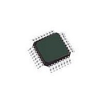
MC9S08JM16CLC Freescale Semiconductor, MC9S08JM16CLC Datasheet - Page 206

MC9S08JM16CLC
Manufacturer Part Number
MC9S08JM16CLC
Description
MCU 8BIT 16K FLASH 32-LQFP
Manufacturer
Freescale Semiconductor
Series
HCS08r
Datasheet
1.DEMO9S08JM16.pdf
(386 pages)
Specifications of MC9S08JM16CLC
Core Processor
HCS08
Core Size
8-Bit
Speed
48MHz
Connectivity
I²C, LIN, SCI, SPI, USB
Peripherals
LVD, POR, PWM, WDT
Number Of I /o
21
Program Memory Size
16KB (16K x 8)
Program Memory Type
FLASH
Ram Size
1K x 8
Voltage - Supply (vcc/vdd)
2.7 V ~ 5.5 V
Data Converters
A/D 4x12b
Oscillator Type
External
Operating Temperature
-40°C ~ 85°C
Package / Case
32-LQFP
Processor Series
S08JM
Core
HCS08
Data Bus Width
8 bit
Data Ram Size
1 KB
Interface Type
I2C, SPI
Maximum Clock Frequency
48 MHz
Number Of Programmable I/os
21
Number Of Timers
2
Operating Supply Voltage
2.7 V to 5.5 V
Maximum Operating Temperature
+ 85 C
Mounting Style
SMD/SMT
3rd Party Development Tools
EWS08
Development Tools By Supplier
DEMOJM, DEMOJMSKT, DEMOFLEXISJMSD, DEMO9S08JM16
Minimum Operating Temperature
- 40 C
On-chip Adc
12 bit, 4 Channel
Controller Family/series
HCS08
No. Of I/o's
21
Ram Memory Size
1KB
Cpu Speed
48MHz
No. Of Timers
2
Digital Ic Case Style
LQFP
Rohs Compliant
Yes
Package
32LQFP
Family Name
HCS08
Maximum Speed
48 MHz
Lead Free Status / RoHS Status
Lead free / RoHS Compliant
Eeprom Size
-
Lead Free Status / Rohs Status
Lead free / RoHS Compliant
Available stocks
Company
Part Number
Manufacturer
Quantity
Price
Company:
Part Number:
MC9S08JM16CLC
Manufacturer:
Freescale Semiconductor
Quantity:
10 000
- Current page: 206 of 386
- Download datasheet (8Mb)
Multi-Purpose Clock Generator (S08MCGV1)
12.5.3
Calibrating the Internal Reference Clock (IRC)
The IRC is calibrated by writing to the MCGTRM register first, then using the FTRIM bit to “fine tune”
the frequency. We will refer to this total 9-bit value as the trim value, ranging from 0x000 to 0x1FF, where
the FTRIM bit is the LSB.
The trim value after a POR is always 0x100 (MCGTRM = 0x80 and FTRIM = 0). Writing a larger value
will decrease the frequency and smaller values will increase the frequency. The trim value is linear with
the period, except that slight variations in wafer fab processing produce slight non-linearities between trim
value and period. These non-linearities are why an iterative trimming approach to search for the best trim
value is recommended. In example #4 later in this section, this approach will be demonstrated.
After a trim value has been found for a device, this value can be stored in FLASH memory to save the
value. If power is removed from the device, the IRC can easily be re-trimmed by copying the saved value
from FLASH to the MCG registers. Freescale identifies recommended FLASH locations for storing the
trim value for each MCU. Consult the memory map in the data sheet for these locations. On devices that
are factory trimmed, the factory trim value will be stored in these locations.
12.5.3.1
Example #5: Internal Reference Clock Trim
For applications that require a tight frequency tolerance, a trimming procedure is provided that will allow
a very accurate internal clock source. This section outlines one example of trimming the internal oscillator.
Many other possible trimming procedures are valid and can be used.
In the example below, the MCG trim will be calibrated for the 9-bit MCGTRM and FTRIM collective
value. This value will be referred to as TRMVAL.
MC9S08JM16 Series Data Sheet, Rev. 2
206
Freescale Semiconductor
Related parts for MC9S08JM16CLC
Image
Part Number
Description
Manufacturer
Datasheet
Request
R
Part Number:
Description:
Manufacturer:
Freescale Semiconductor, Inc
Datasheet:
Part Number:
Description:
Manufacturer:
Freescale Semiconductor, Inc
Datasheet:
Part Number:
Description:
Manufacturer:
Freescale Semiconductor, Inc
Datasheet:
Part Number:
Description:
Manufacturer:
Freescale Semiconductor, Inc
Datasheet:
Part Number:
Description:
Manufacturer:
Freescale Semiconductor, Inc
Datasheet:
Part Number:
Description:
Manufacturer:
Freescale Semiconductor, Inc
Datasheet:
Part Number:
Description:
Manufacturer:
Freescale Semiconductor, Inc
Datasheet:
Part Number:
Description:
Manufacturer:
Freescale Semiconductor, Inc
Datasheet:
Part Number:
Description:
Manufacturer:
Freescale Semiconductor, Inc
Datasheet:
Part Number:
Description:
Manufacturer:
Freescale Semiconductor, Inc
Datasheet:
Part Number:
Description:
Manufacturer:
Freescale Semiconductor, Inc
Datasheet:
Part Number:
Description:
Manufacturer:
Freescale Semiconductor, Inc
Datasheet:
Part Number:
Description:
Manufacturer:
Freescale Semiconductor, Inc
Datasheet:
Part Number:
Description:
Manufacturer:
Freescale Semiconductor, Inc
Datasheet:
Part Number:
Description:
Manufacturer:
Freescale Semiconductor, Inc
Datasheet:


