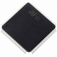
ST10F269Z2T3 STMicroelectronics, ST10F269Z2T3 Datasheet - Page 31

ST10F269Z2T3
Manufacturer Part Number
ST10F269Z2T3
Description
MCU 16BIT 256KBIT FLASH 144-TQFP
Manufacturer
STMicroelectronics
Series
ST10r
Datasheet
1.ST10F269Z2Q3.pdf
(184 pages)
Specifications of ST10F269Z2T3
Core Processor
ST10
Core Size
16-Bit
Speed
40MHz
Connectivity
CAN, EBI/EMI, SSC, UART/USART
Peripherals
POR, PWM, WDT
Number Of I /o
111
Program Memory Size
256KB (256K x 8)
Program Memory Type
FLASH
Ram Size
12K x 8
Voltage - Supply (vcc/vdd)
4.5 V ~ 5.5 V
Data Converters
A/D 16x10b
Oscillator Type
Internal
Operating Temperature
-40°C ~ 125°C
Package / Case
144-TQFP, 144-VQFP
Processor Series
ST10F26x
Core
ST10
Data Bus Width
16 bit
Data Ram Size
12 KB
Interface Type
CAN, SSC, USART
Maximum Clock Frequency
40 MHz
Number Of Programmable I/os
111
Number Of Timers
5
Maximum Operating Temperature
+ 125 C
Mounting Style
SMD/SMT
Minimum Operating Temperature
- 40 C
On-chip Adc
10 bit, 16 Channel
Lead Free Status / RoHS Status
Lead free / RoHS Compliant
Eeprom Size
-
Lead Free Status / Rohs Status
Details
Available stocks
Company
Part Number
Manufacturer
Quantity
Price
Company:
Part Number:
ST10F269Z2T3
Manufacturer:
LITTLEFUSE
Quantity:
1 000
Company:
Part Number:
ST10F269Z2T3
Manufacturer:
STMicroelectronics
Quantity:
10 000
ST10F269
....
5.6 - Bootstrap Loader
The built-in bootstrap loader (BSL) of the
ST10F269 provides a mechanism to load the
startup program through the serial interface after
reset. In this case, no external memory or internal
Flash memory is required for the initialization
code starting at location 00’0000h (see Figure 5).
The bootstrap loader moves code/data into the
internal RAM, but can also transfer data via the
serial interface into an external RAM using a
second level loader routine. Flash Memory
(internal or external) is not necessary, but it may
be used to provide lookup tables or “core-code”
like a set of general purpose subroutines for I/O
operations,
initialization, etc.
The bootstrap loader can be used to load the
complete application software into ROMless
systems,
complete systems for testing or calibration, or to
load a programming routine for Flash devices.
The BSL mechanism can be used for standard
system startup as well as for special occasions
like system maintenance (firmer update) or
end-of-line programming or testing.
Figure 5 : Bootstrap Loader Sequence
CSP:IP
RSTIN
1) BSL initialization time
2) Zero Byte (1 start bit, eight ‘0’ data bits, 1 stop bit), sent by host.
3) Identification Byte (D5h), sent by ST10F269.
4) 32 Bytes of code / data, sent by host.
5) Caution: TxD0 is only driven a certain time after reception of the zero Byte.
6) Internal Boot ROM.
P0L.4
RxD0
TxD0
to
number
load
temporary
crunching,
1)
6)
2)
software
Internal Boot Memory (BSL) routine
5)
system
into
3)
5.6.1 - Entering the Bootstrap Loader
The ST10F269 enters BSL mode when pin P0L.4
is sampled low at the end of a hardware reset. In
this case the built-in bootstrap loader is activated
independent of the selected bus mode.
The bootstrap loader code is stored in a special
Boot-ROM. No part of the standard mask Memory
or Flash Memory area is required for this.
After entering BSL mode and the respective
initialization the ST10F269 scans the RXD0 line to
receive a zero Byte, one start bit, eight ‘0’ data bits
and one stop bit.
From the duration of this zero Byte it calculates
the corresponding Baud rate factor with respect to
the current CPU clock, initializes the serial
interface ASC0 accordingly and switches pin
TxD0 to output.
Using this Baud rate, an identification Byte is
returned to the host that provides the loaded data.
This identification Byte identifies the device to
be booted. The identification byte is D5h for
ST10F269.
4)
5 - INTERNAL FLASH MEMORY
32 Byte user software
31/184


