ST72F63BK4B1 STMicroelectronics, ST72F63BK4B1 Datasheet - Page 32
ST72F63BK4B1
Manufacturer Part Number
ST72F63BK4B1
Description
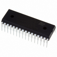
IC MCU 8BIT 16K FLASH 32-SDIP
Manufacturer
STMicroelectronics
Series
ST7r
Datasheet
1.ST72F63BD6U1TR.pdf
(186 pages)
Specifications of ST72F63BK4B1
Core Processor
ST7
Core Size
8-Bit
Speed
8MHz
Connectivity
I²C, SCI, USB
Peripherals
DMA, LVD, POR, PWM, WDT
Number Of I /o
19
Program Memory Size
16KB (16K x 8)
Program Memory Type
FLASH
Ram Size
512 x 8
Voltage - Supply (vcc/vdd)
4 V ~ 5.5 V
Data Converters
A/D 12x8b
Oscillator Type
External
Operating Temperature
0°C ~ 70°C
Package / Case
32-SDIP (0.400", 10.16mm)
Processor Series
ST72F6x
Core
ST7
Data Bus Width
8 bit
Data Ram Size
512 B
Interface Type
I2C, SCI
Maximum Clock Frequency
8 MHz
Number Of Programmable I/os
19
Number Of Timers
1
Maximum Operating Temperature
+ 70 C
Mounting Style
Through Hole
Development Tools By Supplier
ST7MDTU3-EPB/US, ST72F63B-SK/RAIS, ST7MDTU3-EMU3, STX-RLINK
Minimum Operating Temperature
0 C
On-chip Adc
8 bit, 8 Channel / 8 bit, 12 Channel
For Use With
497-5521 - EVAL BOARD LOW SPEED USB
Lead Free Status / RoHS Status
Lead free / RoHS Compliant
Eeprom Size
-
Lead Free Status / Rohs Status
Details


Reset and clock management
6
6.1
Caution:
6.1.1
6.1.2
6.1.3
32/186
Reset and clock management
Reset
The Reset procedure is used to provide an orderly software start-up or to exit low power
modes.
Three reset modes are provided: a low voltage (LVD) reset, a watchdog reset and an
external reset at the RESET pin.
A reset causes the reset vector to be fetched from addresses FFFEh and FFFFh in order to
be loaded into the PC and with program execution starting from this point.
An internal circuitry provides a 4096 CPU clock cycle delay from the time that the oscillator
becomes active.
When the ST7 is unprogrammed or fully erased, the Flash is blank and the RESET vector is
not programmed. For this reason, it is recommended to keep the RESET pin in low state
until programming mode is entered, in order to avoid unwanted behavior.
Low voltage detector (LVD)
Low voltage reset circuitry generates a reset when V
●
●
During low voltage reset, the RESET pin is held low, thus permitting the MCU to reset other
devices.
It is recommended to make sure that the V
device is exiting from Reset, to ensure the application functions properly.
Watchdog reset
When a watchdog reset occurs, the RESET pin is pulled low permitting the MCU to reset
other devices in the same way as the low voltage reset
External reset
The external reset is an active low input signal applied to the RESET pin of the MCU.
As shown in
CPU clock cycles.
An internal Schmitt trigger at the RESET pin is provided to improve noise immunity.
Below V
Below V
Figure
IT+
IT-
when V
when V
15, the RESET signal must stay low for a minimum of one and a half
DD
DD
is falling
is rising
Doc ID 7516 Rev 8
DD
supply voltage rises monotonously when the
DD
(Figure
is:
12).
ST7263Bxx
Related parts for ST72F63BK4B1
Image
Part Number
Description
Manufacturer
Datasheet
Request
R

Part Number:
Description:
KIT STARTER LOW COST ST7
Manufacturer:
STMicroelectronics
Datasheet:

Part Number:
Description:
LOW SPEED USB 8-BIT MCU FAMILY WITH FLASH/ROM, UP TO 512 BYTES RAM, 8-BIT ADC, WDG, TIMER, SCI & I�C
Manufacturer:
STMICROELECTRONICS [STMicroelectronics]
Datasheet:
Part Number:
Description:
STMicroelectronics [RIPPLE-CARRY BINARY COUNTER/DIVIDERS]
Manufacturer:
STMicroelectronics
Datasheet:
Part Number:
Description:
STMicroelectronics [LIQUID-CRYSTAL DISPLAY DRIVERS]
Manufacturer:
STMicroelectronics
Datasheet:

Part Number:
Description:
BOARD EVAL FOR MEMS SENSORS
Manufacturer:
STMicroelectronics
Datasheet:
Part Number:
Description:
NPN TRANSISTOR POWER MODULE
Manufacturer:
STMicroelectronics
Datasheet:
Part Number:
Description:
TURBOSWITCH ULTRA-FAST HIGH VOLTAGE DIODE
Manufacturer:
STMicroelectronics
Datasheet:
Part Number:
Description:
Manufacturer:
STMicroelectronics
Datasheet:
Part Number:
Description:
DIODE / SCR MODULE
Manufacturer:
STMicroelectronics
Datasheet:
Part Number:
Description:
DIODE / SCR MODULE
Manufacturer:
STMicroelectronics
Datasheet:
Part Number:
Description:
Search -----> STE16N100
Manufacturer:
STMicroelectronics
Datasheet:
Part Number:
Description:
Search ---> STE53NA50
Manufacturer:
STMicroelectronics
Datasheet: