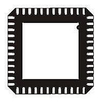
STM32F103C6U6A STMicroelectronics, STM32F103C6U6A Datasheet - Page 68

STM32F103C6U6A
Manufacturer Part Number
STM32F103C6U6A
Description
MCU 32BIT ARM 32K FLASH 48-QFN
Manufacturer
STMicroelectronics
Series
STM32r
Datasheet
1.STM32F103C4T6A.pdf
(87 pages)
Specifications of STM32F103C6U6A
Core Processor
ARM® Cortex-M3™
Core Size
32-Bit
Speed
72MHz
Connectivity
CAN, I²C, IrDA, LIN, SPI, UART/USART, USB
Peripherals
DMA, Motor Control PWM, PDR, POR, PVD, PWM, Temp Sensor, WDT
Number Of I /o
37
Program Memory Size
32KB (32K x 8)
Program Memory Type
FLASH
Ram Size
10K x 8
Voltage - Supply (vcc/vdd)
2 V ~ 3.6 V
Data Converters
A/D 10x12b
Oscillator Type
Internal
Operating Temperature
-40°C ~ 85°C
Package / Case
48-LQFP
Processor Series
STM32F103x
Core
ARM Cortex M3
Data Bus Width
32 bit
Data Ram Size
10 KB
Interface Type
CAN, I2C, SPI, USART
Maximum Clock Frequency
72 MHz
Number Of Programmable I/os
37
Number Of Timers
6
Operating Supply Voltage
2 V to 3.6 V
Maximum Operating Temperature
+ 85 C
Mounting Style
SMD/SMT
3rd Party Development Tools
EWARM, EWARM-BL, MDK-ARM, RL-ARM, ULINK2
Minimum Operating Temperature
- 40 C
On-chip Adc
12 bit, 10 Channel
For Use With
497-10030 - STARTER KIT FOR STM32497-8511 - KIT STARTER FOR STM32 512K FLASH497-6438 - BOARD EVALUTION FOR STM32 512K
Lead Free Status / RoHS Status
Lead free / RoHS Compliant
Eeprom Size
-
Lead Free Status / Rohs Status
Details
Available stocks
Company
Part Number
Manufacturer
Quantity
Price
Electrical characteristics
5.3.17
68/87
Table 44.
1. All the voltages are measured from the local ground potential.
2. To be compliant with the USB 2.0 full-speed electrical specification, the USBDP (D+) pin should be pulled
3. The STM32F103xx USB functionality is ensured down to 2.7 V but not the full USB electrical
4. Guaranteed by design, not tested in production.
5. R
Figure 33. USB timings: definition of data signal rise and fall time
Table 45.
1. Guaranteed by design, not tested in production.
2. Measured from 10% to 90% of the data signal. For more detailed informations, please refer to USB
CAN (controller area network) interface
Refer to
input/output alternate function characteristics (CAN_TX and CAN_RX).
Input levels
Output levels
Driver characteristics
Symbol
V
Symbol
V
V
V
V
V
up with a 1.5 k Ω resistor to a 3.0-to-3.6 V voltage range.
characteristics which are degraded in the 2.7-to-3.0 V V
V
Specification - Chapter 7 (version 2.0).
CM
SE
DI
t
OH
DD
OL
L
CRS
rfm
t
t
(4)
r
f
(4)
(4)
is the load connected on the USB drivers
Section 5.3.12: I/O current injection characteristics
USB operating voltage
Differential input sensitivity
Differential common mode range
Single ended receiver threshold
Static output level low
Static output level high
data lines
Differen tial
Rise time
Fall time
Rise/ fall time matching
Output signal crossover voltage
USB DC electrical characteristics
USB: Full-speed electrical characteristics
V CRS
V S S
(2)
(2)
Parameter
Parameter
t f
Doc ID 15060 Rev 5
(2)
Crossover
points
t r
R
R
L
I(USBDP, USBDM)
Includes V
L
Conditions
of 1.5 k
C
C
of 15 k
L
L
DD
Conditions
= 50 pF
= 50 pF
t
r
voltage range.
/t
f
Ω
Ω
(1)
DI
to 3.6 V
to V
range
SS
for more details on the
STM32F103x4, STM32F103x6
(5)
(5)
Min
1.3
90
4
4
Min.
3.0
0.2
0.8
1.3
2.8
(3)
(1)
Max
110
2.0
20
20
Max.
ai14137
2.0
3.6
2.5
0.3
3.6
(1)
Unit
ns
ns
%
V
Unit
V
V
V


