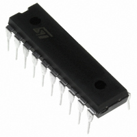
ST7FLITE20F1B6 STMicroelectronics, ST7FLITE20F1B6 Datasheet - Page 210

ST7FLITE20F1B6
Manufacturer Part Number
ST7FLITE20F1B6
Description
IC MCU 8BIT 8K FLASH 20-DIP
Manufacturer
STMicroelectronics
Series
ST7r
Specifications of ST7FLITE20F1B6
Core Processor
ST7
Core Size
8-Bit
Speed
8MHz
Connectivity
SPI
Peripherals
LVD, POR, PWM, WDT
Number Of I /o
15
Program Memory Size
8KB (8K x 8)
Program Memory Type
FLASH
Ram Size
384 x 8
Voltage - Supply (vcc/vdd)
2.4 V ~ 5.5 V
Data Converters
A/D 7x10b
Oscillator Type
Internal
Operating Temperature
-40°C ~ 85°C
Package / Case
20-DIP (0.300", 7.62mm)
Processor Series
ST7FLITE2x
Core
ST7
Data Bus Width
8 bit
Development Tools By Supplier
ST7FLITE-SK/RAIS, ST7MDT10-DVP3, ST7MDT10-EMU3, STX-RLINK
For Use With
497-5858 - EVAL BOARD PLAYBACK ST7FLITE497-5517 - EVAL BOARD 1PHASE ENERGY METER497-5049 - KIT STARTER RAISONANCE ST7FLITE
Lead Free Status / RoHS Status
Lead free / RoHS Compliant
Eeprom Size
-
Lead Free Status / Rohs Status
Details
Available stocks
Company
Part Number
Manufacturer
Quantity
Price
- Current page: 210 of 235
- Download datasheet (2Mb)
Function Descriptions
Table 158. MCC_RTC_Timer
Notes:
– The MCC/ RTC interrupt wakes up the MCU from ACTIVE-HALT mode, not from HALT
– A modification of time base is taken into account at the end of the current period (previously
Notes:
The timebase for other f
For example, if f
210/235
Function Name
Function Prototype
Behaviour Description
Input Parameters
Output Parameters
Required Preconditions
Functions called
Postconditions
See also
mode.
set), to avoid an unwanted time shift.
For MCC_RTC_0, Timebase = 32000/(2*f
For MCC_RTC_1, Timebase = 64000/(2*f
For MCC_RTC_2, Timebase = 160000/(2*f
For MCC_RTC_3, Timebase = 400000/(2*f
follows.
For MCC_RTC_0, Timebase = 3.2 ms,
For MCC_RTC_1, Timebase = 6.4 ms,
For MCC_RTC_2, Timebase =16 ms,
For MCC_RTC_3, Timebase = 40 ms.
MCC_RTC_X
MCC_RTC_0
MCC_RTC_1
MCC_RTC_2
MCC_RTC_3
OSC2
= 5MHz, for the MCC_RTC_X input values, the timebase values are as
Timebase for
f
OSC2
OSC2
200ms
16ms
32ms
80ms
= 1MHz
can be reached by calculation, as shown below.
MCC_RTC_Timer
Void MCC_RTC_Timer (MCC_RTC_Param Timer_Value)
Selects the programmable divider time base. Oscillator in-
terrupts are generated, as per the timebase selection. You
have to select the input values from the table shown be-
low.
MCC_RTC_X
x= 0,1,2,3.
You have to select values, to decide the time base for os-
cillator interrupt.
None
MCC_Init must have been called.
None
None
None
Timebase for
f
OSC2
OSC2
OSC2
100ms
OSC2
OSC2
16ms
40ms
8ms
= 2MHz
).
).
).
).
Timebase for
f
OSC2
20ms
50ms
4ms
8ms
= 4MHz
Timebase for
f
OSC2
10ms
25ms
2ms
4ms
= 8MHz
Related parts for ST7FLITE20F1B6
Image
Part Number
Description
Manufacturer
Datasheet
Request
R

Part Number:
Description:
MCU, MPU & DSP Development Tools Eval for ST7FLIT2
Manufacturer:
STMicroelectronics
Datasheet:

Part Number:
Description:
KIT STARTER RAISONANCE ST7FLITE
Manufacturer:
STMicroelectronics
Datasheet:

Part Number:
Description:
STMicroelectronics [RIPPLE-CARRY BINARY COUNTER/DIVIDERS]
Manufacturer:
STMicroelectronics
Datasheet:

Part Number:
Description:
STMicroelectronics [LIQUID-CRYSTAL DISPLAY DRIVERS]
Manufacturer:
STMicroelectronics
Datasheet:

Part Number:
Description:
BOARD EVAL FOR MEMS SENSORS
Manufacturer:
STMicroelectronics
Datasheet:

Part Number:
Description:
NPN TRANSISTOR POWER MODULE
Manufacturer:
STMicroelectronics
Datasheet:

Part Number:
Description:
TURBOSWITCH ULTRA-FAST HIGH VOLTAGE DIODE
Manufacturer:
STMicroelectronics
Datasheet:

Part Number:
Description:
Manufacturer:
STMicroelectronics
Datasheet:

Part Number:
Description:
DIODE / SCR MODULE
Manufacturer:
STMicroelectronics
Datasheet:

Part Number:
Description:
DIODE / SCR MODULE
Manufacturer:
STMicroelectronics
Datasheet:

Part Number:
Description:
Search -----> STE16N100
Manufacturer:
STMicroelectronics
Datasheet:

Part Number:
Description:
Search ---> STE53NA50
Manufacturer:
STMicroelectronics
Datasheet:


