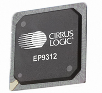
EP9312-IB Cirrus Logic Inc, EP9312-IB Datasheet - Page 8

EP9312-IB
Manufacturer Part Number
EP9312-IB
Description
IC ARM920T MCU 200MHZ 352-PBGA
Manufacturer
Cirrus Logic Inc
Series
EP9r
Datasheets
1.EP9307-CRZ.pdf
(824 pages)
2.EP9312-IBZ.pdf
(4 pages)
3.EP9312-CB.pdf
(62 pages)
4.EP9312-CB.pdf
(17 pages)
Specifications of EP9312-IB
Core Processor
ARM9
Core Size
16/32-Bit
Speed
200MHz
Connectivity
EBI/EMI, EIDE, Ethernet, I²C, IrDA, Keypad/Touchscreen, SPI, UART/USART, USB
Peripherals
AC'97, DMA, I²:S, LCD, LED, MaverickKey, POR, PWM, WDT
Number Of I /o
16
Program Memory Type
ROMless
Ram Size
32K x 8
Voltage - Supply (vcc/vdd)
1.65 V ~ 3.6 V
Data Converters
A/D 8x12b
Oscillator Type
External
Operating Temperature
-40°C ~ 85°C
Package / Case
352-BGA
Processor Series
EP93xx
Core
ARM920T
Data Bus Width
32 bit
3rd Party Development Tools
MDK-ARM, RL-ARM, ULINK2
Lead Free Status / RoHS Status
Contains lead / RoHS non-compliant
Eeprom Size
-
Program Memory Size
-
Lead Free Status / Rohs Status
No
Other names
598-1259
Available stocks
Company
Part Number
Manufacturer
Quantity
Price
Company:
Part Number:
EP9312-IBZ
Manufacturer:
CIRRUS
Quantity:
30
Company:
Part Number:
EP9312-IBZ
Manufacturer:
HITTITE
Quantity:
1 200
EP9312
Universal Platform SOC Processor
LCD-specific features include:
•
•
•
•
•
•
•
•
Touch Screen Interface with 12-bit Analog-
to-digital Converter (ADC)
The touch screen interface performs all sampling,
averaging, ADC range checking, and control for a wide
variety of analog resistive touch screens. This controller
only interrupts the processor when a meaningful change
occurs. The touch screen hardware may be disabled and
the switch matrix and ADC controlled directly if desired.
Features include:
•
•
•
8
SPCLK
P[17:0]
HSYNC / LP
VCSYNC / FP
BLANK
BRIGHT
Xp, Xm
Table G. Touch Screen Interface with 12-bit Analog-to-Digital
Timing and interface signals for digital LCD and TFT
displays
Full programmability for either non-interlaced or dual-
scan color and grayscale flat panel displays
Dedicated data path to SDRAM controller for
improved system performance
Pixel depths of 4, 8, 16, or 24 bits per pixel or 256
levels of grayscale
Hardware Cursor up to 64 x 64 pixels
256 x 18 Color Lookup Table
Hardware Blinking
8-bit interface to low-end panel
Support for 4-, 5-, 7-, or 8-wire analog resistive touch
screens.
Flexibility - unused lines may be used for temperature
sensing or other functions.
Touch screen interrupt function.
Pin Mnemonic
Pin Mnemonic
Table F. LCD Interface Pin Assignments
Converter Pin Assignments
Pixel Clock
Pixel Data Bus [17:0]
Horizontal
Synchronization / Line Pulse
Vertical or Composite
Synchronization / Frame Pulse
Composite Blank
Pulse Width Modulated Brightness
Touch screen ADC X Axis
Pin Description
Pin Description
©
Copyright 2005 Cirrus Logic (All Rights Reserved)
64-Key Keypad Interface
The keypad circuitry scans an 8 x 8 array of 64 normally
open, single-pole switches. Any one or two keys
depressed will be de-bounced and decoded. An interrupt
is generated whenever a stable set of depressed keys is
detected. If the keypad is not utilized, the 16 column/row
pins may be used as general purpose I/O. The Keypad
interface:
•
•
•
•
•
Universal Asynchronous
Receiver/Transmitters (UARTs)
Three 16550-compatible UARTs are supplied. Two
provide asynchronous HDLC (High-level Data Link
Control) protocol support for full duplex transmit and
receive. The HDLC receiver handles framing, address
matching, CRC checking, control-octet transparency, and
optionally passes the CRC to the host at the end of the
packet. The HDLC transmitter handles framing, CRC
generation, and control-octet transparency. The host
must
transmission. The HDLC receiver and transmitter use the
UART FIFOs to buffer the data streams. A third IrDA
compatible UART is also supplied.
•
Yp, Ym
SXp, SXm
SYp, SYm
COL[7:0]
ROW[7:0]
Pin Mnemonic
Table G. Touch Screen Interface with 12-bit Analog-to-Digital
Provides scanning, debounce, and decoding for a 64-
key switch array.
Scans an 8-row by 8-column matrix.
May decode 2 keys at once.
Generates an interrupt when a new stable key is
determined.
Also generates a 3-key reset interrupt.
UART1 supports modem bit rates up to 115.2 Kbps,
supports HDLC and includes a 16 byte FIFO for
Pin Mnemonic
Table H. 64-Key Keypad Interface Pin Assignments
assemble
Converter Pin Assignments
Key Matrix Column
Inputs
Key Matrix Row
Inputs
the
Description
Touch screen ADC Y Axis
Touch screen ADC X Axis
Voltage Feedback
Touch screen ADC Y Axis
Voltage Feedback
Pin
frame
Pin Description
in
General Purpose I/O
General Purpose I/O
Alternative Usage
memory
DS515PP7
before
®


