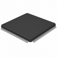
LH75411N0Q100C0;55 NXP Semiconductors, LH75411N0Q100C0;55 Datasheet - Page 34

LH75411N0Q100C0;55
Manufacturer Part Number
LH75411N0Q100C0;55
Description
IC ARM7 BLUESTREAK MCU 144LQFP
Manufacturer
NXP Semiconductors
Series
BlueStreak ; LH7r
Datasheet
1.LH75401N0Q100C055.pdf
(63 pages)
Specifications of LH75411N0Q100C0;55
Package / Case
144-LQFP
Core Processor
ARM7
Core Size
16/32-Bit
Speed
84MHz
Connectivity
EBI/EMI, SPI, SSI, SSP, UART/USART
Peripherals
Brown-out Detect/Reset, DMA, LCD, POR, PWM, WDT
Number Of I /o
76
Program Memory Type
ROMless
Ram Size
32K x 8
Voltage - Supply (vcc/vdd)
1.7 V ~ 3.6 V
Data Converters
A/D 8x10b
Oscillator Type
External
Operating Temperature
-40°C ~ 85°C
Processor Series
LH75
Core
ARM7TDMI-S
Data Bus Width
32 bit
Data Ram Size
32 KB
Interface Type
JTAG, SPI, UART
Maximum Clock Frequency
84 MHz
Number Of Programmable I/os
76
Number Of Timers
3
Operating Supply Voltage
3.3 V
Maximum Operating Temperature
+ 85 C
Mounting Style
SMD/SMT
3rd Party Development Tools
MDK-ARM, RL-ARM, ULINK2
Minimum Operating Temperature
- 40 C
On-chip Adc
10 bit, 8 Channel
Lead Free Status / RoHS Status
Lead free / RoHS Compliant
Eeprom Size
-
Program Memory Size
-
Lead Free Status / Rohs Status
Lead free / RoHS Compliant
Other names
568-4330
935285046557
935285046557
LH75401/LH75411
ELECTRICAL SPECIFICATIONS
NOTE: These ratings are only for transient conditions. Operation at
NOTES:
1. Core Voltage should never exceed I/O Voltage after initial power up. See the section titled ‘Power Supply Sequencing’.
2. Connect VDDA1 to VDDC when using the on-chip linear regulator.
3. On-chip Linear regulator enabled. When the on-chip linear regulator is enabled, Core power is drawn from VDD – allow VDDC pins to float.
4. Will operate to DC with PLL disabled. Core frequencies greater than 84 MHz require external clock and VDDC. Core frequencies faster than
5. Processor is functional at minimum frequency, but not all peripherals may be enabled.
6. The maximum operating frequency is the crystal frequency × 3.5.
NOTES:
1. On-chip Linear regulator and PLL disabled; VDDC supplied externally.
2. Core speeds greater than 84 MHz require external VDDC and may not yield proper UART baud rates.
3. Core speeds greater than 70 MHz require an external clock.
4. Additional performance may be achieved in accordance with Figure 5.
34
DC Core Supply Voltage (VDDC)
DC I/O Supply Voltage (VDD)
DC Analog Supply Voltage for ADC (VDDA0)
DC Analog Supply Voltage for PLL (VDDA1)
Storage Temperature (TSTG)
DC Core Supply Voltage (VDDC) (Linear Regulator disabled)
DC Analog Supply Voltage for ADC (VDDA0)
DC I/O Supply Voltage (VDD)
DC Analog Supply Voltage for PLL (VDDA1)
Clock Frequency (ƒHCLK)
Clock Period (tHCLK)
Crystal Frequency
Industrial Operating Temperature
25°C
70°C
85°C
70 MHz require an externally-supplied clock.
Table 18. Clock Frequency vs. Voltages (VDDC) vs. Temperature
or beyond absolute maximum rating conditions may affect
reliability and cause permanent damage to the device.
Clock Frequency (ƒHCLK)
Clock Period (tHCLK)
Clock Frequency (ƒHCLK)
Clock Period (tHCLK)
Clock Frequency (ƒHCLK)
Clock Period (tHCLK)
PARAMETER
Table 16. Absolute Maximum Ratings
PARAMETER
PARAMETER
Table 17. Recommended Operating Conditions
11.9047 ns
10.952 ns
11.627 ns
91.3 MHz
86 MHz
84 MHz
1.7 V
NXP Semiconductors
Rev. 01 — 16 July 2007
MINIMUM MAXIMUM
-0.3 V
-0.3 V
-0.3 V
-0.3 V
-55°C
10.309 ns
10.869 ns
11.111 ns
97 MHz
92 MHz
90 MHz
1.8 V
125°C
4.6 V
2.4 V
4.6 V
2.4 V
4.375 MHz
11.9047 ns
MINIMUM
103.7 MHz
14 MHz
10.266 ns
10.504 ns
97.4 MHz
95.2 MHz
−40°C
9.643 ns
1.7 V
3.0 V
3.0 V
1.7 V
1.9 V
1.8 V
3.3 V
3.3 V
1.8 V
25°C
TYP.
Preliminary data sheet
228.571 ns
MAXIMUM
84 MHz
20 MHz
1.98 V
1.98 V
3.6 V
3.6 V
85°C
System-on-Chip
NOTES
3, 4, 5
3, 4, 5
4, 5
1
1
2


