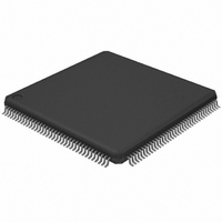
LH75411N0Q100C0;55 NXP Semiconductors, LH75411N0Q100C0;55 Datasheet - Page 32

LH75411N0Q100C0;55
Manufacturer Part Number
LH75411N0Q100C0;55
Description
IC ARM7 BLUESTREAK MCU 144LQFP
Manufacturer
NXP Semiconductors
Series
BlueStreak ; LH7r
Datasheet
1.LH75401N0Q100C055.pdf
(63 pages)
Specifications of LH75411N0Q100C0;55
Package / Case
144-LQFP
Core Processor
ARM7
Core Size
16/32-Bit
Speed
84MHz
Connectivity
EBI/EMI, SPI, SSI, SSP, UART/USART
Peripherals
Brown-out Detect/Reset, DMA, LCD, POR, PWM, WDT
Number Of I /o
76
Program Memory Type
ROMless
Ram Size
32K x 8
Voltage - Supply (vcc/vdd)
1.7 V ~ 3.6 V
Data Converters
A/D 8x10b
Oscillator Type
External
Operating Temperature
-40°C ~ 85°C
Processor Series
LH75
Core
ARM7TDMI-S
Data Bus Width
32 bit
Data Ram Size
32 KB
Interface Type
JTAG, SPI, UART
Maximum Clock Frequency
84 MHz
Number Of Programmable I/os
76
Number Of Timers
3
Operating Supply Voltage
3.3 V
Maximum Operating Temperature
+ 85 C
Mounting Style
SMD/SMT
3rd Party Development Tools
MDK-ARM, RL-ARM, ULINK2
Minimum Operating Temperature
- 40 C
On-chip Adc
10 bit, 8 Channel
Lead Free Status / RoHS Status
Lead free / RoHS Compliant
Eeprom Size
-
Program Memory Size
-
Lead Free Status / Rohs Status
Lead free / RoHS Compliant
Other names
568-4330
935285046557
935285046557
LH75401/LH75411
Reset, Clock, and Power Controller (RCPC)
power management, and external interrupt condition-
ing via the AMBA APB interface. This control includes:
• Enabling and disabling various clocks
• Managing power-down sequencing
• Selecting the sources for various clocks.
crystal oscillator stabilizes and the PLL acquires lock. If
users want to change the system clock frequency dur-
ing normal operation, the RCPC ensures a seamless
transition between the old and new frequencies.
RCPC FEATURES
• Manages five Power Modes for minimizing power
• Generates the system clock (HCLK) from either the
• Generates three UART clocks from oscillator clock
• Generates the 1 Hz RTC clock
• Generates the SSP and LCD clocks from HCLK,
• Provides a selectable external clock output
• Generates system and RTC Resets based on an
• Configures seven HIGH/LOW-level or rising/falling
• Generates remap outputs used by the memory map
• Provides an identification register
• Supports external or watchdog reset status.
Operating Modes
three operating modes:
• Normal Mode
• PLL Bypass Mode, where the internal PLL is
• EmbeddedICE
32
consumption: Active, Standby, Sleep, Stop1, and
Stop2
PLL clock or the PLL-bypassed (oscillator) clock,
divided by 2, 4, 6, 8, … 30
divided by 1, 2, 4, 8, 16, 32, or 64
external reset, Watchdog Timer reset, or soft reset
edge-trigger external interrupts and converts them to
HIGH-level trigger interrupt outputs required by the VIC
decoder
bypassed and an external clock source is used; oth-
erwise the chip operates normally
accesses the TAP Controller in the core and the core
is placed in Debug Mode.
The RCPC lets users control System Reset, clocks,
The RCPC provides for an orderly start-up until the
The LH75401/LH75411 microcontrollers support
Mode,
where
the
JTAG
NXP Semiconductors
Rev. 01 — 16 July 2007
port
nals determines the operating mode entered at Power-
on Reset (see Table 12).
NOTE: TEST1, TEST2, and nRESETIN are latched on the rising
General Purpose Input/Output (GPIO)
GPIO ports:
• Seven 8-bit ports
• Two 7-bit ports
• One 6-bit port.
vide 76 bits of programmable input/output (see Table
13). Pins of all ports, except Port J, can be configured
as inputs or outputs. Port J is input only. Upon System
Reset, all ports default to inputs.
Reserved
PLL Bypass
Reserved
Reserved
EmbeddedICE
Normal
OPERATING MODE
The state of the TEST1, TEST2, and nRESETIN sig-
The LH75401/LH75411 microcontrollers have 10
The GPIO ports are designated A through J and pro-
PORT
C
D
G
H
A
B
E
F
J
I
edge of nPOR. The microcontroller stays in that operating
mode until power is removed or nPOR transitions from LOW
to HIGH.
Table 12. Device Operating Modes
Table 13. GPIO Ports
PROGRAMMABLE PINS
TEST2
8 Input/Output Pins
6 Input/Output Pins
8 Input/Output Pins
7 Input/Output Pins
8 Input/Output Pins
7 Input/Output Pins
8 Input/Output Pins
8 Input/Output Pins
8 Input/Output Pins
0
0
0
1
1
1
8 Input Pins
Preliminary data sheet
TEST1
0
0
1
0
0
1
System-on-Chip
nRESETIN
0
1
0
1
x
x


