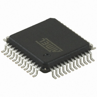
AT32UC3L064-AUT Atmel, AT32UC3L064-AUT Datasheet - Page 70

AT32UC3L064-AUT
Manufacturer Part Number
AT32UC3L064-AUT
Description
MCU AVR32 64KB FLASH 48TQFP
Manufacturer
Atmel
Series
AVR®32 UC3r
Datasheets
1.ATAVRONE-PROBECBL.pdf
(16 pages)
2.AT32UC3L-EK.pdf
(858 pages)
3.AT32UC3L016-D3HT.pdf
(110 pages)
Specifications of AT32UC3L064-AUT
Core Processor
AVR
Core Size
32-Bit
Speed
50MHz
Connectivity
I²C, SPI, UART/USART
Peripherals
Brown-out Detect/Reset, DMA, PWM, WDT
Number Of I /o
36
Program Memory Size
64KB (64K x 8)
Program Memory Type
FLASH
Ram Size
16K x 8
Voltage - Supply (vcc/vdd)
1.62 V ~ 3.6 V
Data Converters
A/D 9x10b
Oscillator Type
Internal
Operating Temperature
-40°C ~ 85°C
Package / Case
48-TQFP, 48-VQFP
Processor Series
AT32UC3x
Core
AVR32
Data Bus Width
32 bit
Data Ram Size
16 KB
Interface Type
SPI/TWI/USART
Maximum Clock Frequency
50 MHz
Number Of Programmable I/os
36
Number Of Timers
7
Maximum Operating Temperature
+ 85 C
Mounting Style
SMD/SMT
3rd Party Development Tools
EWAVR32, EWAVR32-BL
Development Tools By Supplier
AT32UC3L-EK
Minimum Operating Temperature
- 40 C
On-chip Adc
9-ch x 10-bit
Package
48TQFP
Device Core
AVR32
Family Name
AT32
Maximum Speed
50 MHz
Operating Supply Voltage
1.8|3.3 V
Lead Free Status / RoHS Status
Lead free / RoHS Compliant
Eeprom Size
-
Lead Free Status / Rohs Status
Lead free / RoHS Compliant
Available stocks
Company
Part Number
Manufacturer
Quantity
Price
Company:
Part Number:
AT32UC3L064-AUT
Manufacturer:
HONGFA
Quantity:
30 000
Part Number:
AT32UC3L064-AUT
Manufacturer:
MICROCHIP/微芯
Quantity:
20 000
7.10.5
Table 7-42.
32099F–11/2010
t
t
t
t
t
t
r
f
HD-STA
SU-STA
SU-STO
HD-DAT
Symbol
TWIM/TWIS Timing
TWCK and TWD rise time
TWCK and TWD fall time
(Repeated) START hold time
(Repeated) START set-up time
STOP set-up time
Data hold time
TWI-Bus Timing Requirements
Parameter
The maximum SPI slave input frequency is given by the following formula:
Where
CPOL and NCPHA.
ter for a description of this clock.
Maximum SPI Frequency, Slave Output Mode
The maximum SPI slave output frequency is given by the following formula:
Where
SPI master setup time. Please refer to the SPI master datasheet for
imum frequency of the SPI pins. Please refer to the I/O Pin Characteristics section for the
maximum frequency of the pins.
Figure 7-42
them. Some of these requirements (t
vention. Compliance with the other requirements (t
TWI
TWIM and TWIS user interface registers. Please refer to the TWIM and TWIS sections for more
information.
, t
HIGH
SPIn
SPIn
, and f
shows the TWI-bus timing requirements and the compliance of the device with
Standard
Fast
Standard
Fast
Standard
Fast
Standard
Fast
Standard
Fast
Standard
Fast
is the MISO delay, SPI6 or SPI9 depending on CPOL and NCPHA.
is the MOSI setup and hold time, SPI7 + SPI8 or SPI10 + SPI11 depending on
TWCK
Mode
(1)
) requires user intervention through appropriate programming of the relevant
f
CLKSPI
(1)
Requirement
f
SPCKMAX
is the maximum frequency of the CLK_SPI. Refer to the SPI chap-
0.3
0.6
4.7
0.6
4.0
0.6
f
4
SPCKMAX
(2)
20 + 0.1C
20 + 0.1C
Minimum
r
=
and t
MIN f
-
-
=
f
) are met by the device without requiring user inter-
b
b
(
MIN f
Device
PINMAX
4t
2t
t
t
clkpb
clkpb
clkpb
clkpb
(
HD-STA
CLKSPI
,
------------------------------------
SPIn
, t
AT32UC3L016/32/64
,
SU-STA
----------- -
SPIn
Requirement
+
1
1
t
SETUP
3.45
)
0.9
, t
SU-STO
()
()
)
Maximum
t
SETUP
1000
, t
300
300
300
-
-
-
HD-DAT
15t
.
f
prescaled
PINMAX
Device
, t
SU-DAT-TWI
t
SETUP
+ t
is the max-
clkpb
, t
is the
Unit
LOW-
μs
μs
μs
μs
ns
ns
70


