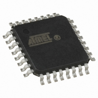
ATMEGA32U2-AU Atmel, ATMEGA32U2-AU Datasheet - Page 38

ATMEGA32U2-AU
Manufacturer Part Number
ATMEGA32U2-AU
Description
IC MCU 8BIT 32KB FLASH 32TQFP
Manufacturer
Atmel
Series
AVR® ATmegar
Specifications of ATMEGA32U2-AU
Core Processor
AVR
Core Size
8-Bit
Speed
16MHz
Connectivity
SPI, UART/USART, USB
Peripherals
Brown-out Detect/Reset, POR, PWM, WDT
Number Of I /o
22
Program Memory Size
32KB (16K x 16)
Program Memory Type
FLASH
Eeprom Size
1K x 8
Ram Size
1K x 8
Voltage - Supply (vcc/vdd)
2.7 V ~ 5.5 V
Oscillator Type
Internal
Operating Temperature
-40°C ~ 85°C
Package / Case
32-TQFP, 32-VQFP
Processor Series
ATMEGA32x
Core
AVR8
Data Bus Width
8 bit
Data Ram Size
1 KB
Interface Type
SPI, UART
Maximum Clock Frequency
16 MHz
Number Of Programmable I/os
22
Number Of Timers
2
Maximum Operating Temperature
+ 85 C
Mounting Style
SMD/SMT
3rd Party Development Tools
EWAVR, EWAVR-BL
Development Tools By Supplier
ATAVRDRAGON, ATSTK500, ATSTK600, ATAVRISP2, ATAVRONEKIT, AT90USBKEY, ATEVK525
Minimum Operating Temperature
- 40 C
Controller Family/series
AVR MEGA
No. Of I/o's
22
Eeprom Memory Size
1KB
Ram Memory Size
1KB
Cpu Speed
16MHz
Rohs Compliant
Yes
Lead Free Status / RoHS Status
Lead free / RoHS Compliant
Data Converters
-
Lead Free Status / Rohs Status
Details
Available stocks
Company
Part Number
Manufacturer
Quantity
Price
- Current page: 38 of 309
- Download datasheet (6Mb)
8.11.2
8.11.3
8.11.4
7799D–AVR–11/10
CLKSEL1 – Clock Selection Register 1
CLKSTA – Clock Status Register
OSCCAL – Oscillator Calibration Register
lator is selected by the fuse bits configuration. The firmware has to check if the clock is correctly
started before selected it.
• Bit 7:4 – RCCKSEL[3:0]: CKSEL for RC oscillator
Clock configuration for the RC Oscillator. After a reset, this part of the register is loaded with the
0010b value that corresponds to the RC oscillator. Modifying this value by firmware before
switching to RC oscillator is prohibited because the RC clock will not start.
• Bit 3:0 – EXCKSEL[3:0]: CKSEL for External oscillator / Low Power Oscillator
Clock configuration for the External Oscillator / Low Power Oscillator. After a reset, if the Exter-
nal oscillator / Low Power Oscillator is selected by fuse bits, this part of the register is loaded
with the fuse configuration. Firmware can modify it to change the start-up time after the clock
switch.
• Bit 7:2 - Res: Reserved bits
These bits are reserved and will always read as zero.
• Bit 1 – RCON: RC Oscillator On
This bit is set by hardware to one if the RC Oscillator is running.
This bit is set by hardware to zero if the RC Oscillator is stoped.
• Bit 0 – EXTON: External Oscillator / Low Power Oscillator On
This bit is set by hardware to one if the External Oscillator / Low Power Oscillator is running.
This bit is set by hardware to zero if the External Oscillator / Low Power Oscillator is stoped.
• Bits 7:0 – CAL[7:0]: Oscillator Calibration Value
The Oscillator Calibration Register is used to trim the Calibrated Internal RC Oscillator to
remove process variations from the oscillator frequency. A pre-programmed calibration value is
automatically written to this register during chip reset, giving the Factory calibrated frequency as
specified in
Bit
(0xD1)
Read/Write
Initial Value
Bit
(0xD2)
Read/Write
Initial Value
Bit
(0x66)
Read/Write
Initial Value
Table 26-1 on page
RCCKSE
R/W
L3
7
0
CAL7
R/W
R
7
7
0
-
RCCKSE
R/W
L2
6
0
CAL6
R/W
R
6
6
0
-
RCCKSE
266. The application software can write this register to change
R/W
L1
CAL5
5
1
R/W
R
5
5
0
-
Device Specific Calibration Value
RCCKSE
R/W
CAL4
L0
0
R/W
4
R
4
4
0
-
EXCKSE
ATmega8U2/16U2/32U2
R/W
CAL3
R/W
L3
3
0
R
3
3
-
EXCKSE
See Bit Description
CAL2
R/W
R/W
L2
2
0
R
2
2
-
EXCKSE
RCON
CAL1
R/W
R/W
L1
R
1
1
1
0
EXCKSE
EXTON
CAL0
R/W
R/W
R
L0
0
0
0
0
OSCCAL
CLKSTA
CLKSEL1
38
Related parts for ATMEGA32U2-AU
Image
Part Number
Description
Manufacturer
Datasheet
Request
R

Part Number:
Description:
Manufacturer:
Atmel Corporation
Datasheet:

Part Number:
Description:
Manufacturer:
ATMEL Corporation
Datasheet:

Part Number:
Description:
IC AVR MCU 32K 16MHZ 5V 44-QFN
Manufacturer:
Atmel
Datasheet:

Part Number:
Description:
IC AVR MCU 32K 16MHZ 5V 40DIP
Manufacturer:
Atmel
Datasheet:

Part Number:
Description:
IC AVR MCU 32K 16MHZ 5V 44TQFP
Manufacturer:
Atmel
Datasheet:

Part Number:
Description:
IC AVR MCU 32K 16MHZ IND 40-DIP
Manufacturer:
Atmel
Datasheet:

Part Number:
Description:
IC AVR MCU 32K 16MHZ IND 44-TQFP
Manufacturer:
Atmel
Datasheet:

Part Number:
Description:
MCU AVR 32KB FLASH 16MHZ 44TQFP
Manufacturer:
Atmel
Datasheet:

Part Number:
Description:
MCU AVR 32KB FLASH 16MHZ 44QFN
Manufacturer:
Atmel
Datasheet:

Part Number:
Description:
MCU AVR 32K FLASH 16MHZ 44-TQFP
Manufacturer:
Atmel
Datasheet:

Part Number:
Description:
IC AVR MCU 32K 16MHZ COM 40-DIP
Manufacturer:
Atmel
Datasheet:

Part Number:
Description:
IC AVR MCU 32K 16MHZ COM 44-QFN
Manufacturer:
Atmel
Datasheet:

Part Number:
Description:
IC AVR MCU 32K 16MHZ COM 44-TQFP
Manufacturer:
Atmel
Datasheet:


