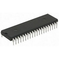
PIC16LF707-I/P Microchip Technology, PIC16LF707-I/P Datasheet - Page 95

PIC16LF707-I/P
Manufacturer Part Number
PIC16LF707-I/P
Description
MCU 8BIT 14KB FLASH 5.5V 40PDIP
Manufacturer
Microchip Technology
Series
PIC® XLP™ 16Fr
Specifications of PIC16LF707-I/P
Core Size
8-Bit
Program Memory Size
14KB (8K x 14)
Peripherals
Brown-out Detect/Reset, POR, PWM, WDT
Core Processor
PIC
Speed
20MHz
Connectivity
I²C, SPI, UART/USART
Number Of I /o
36
Program Memory Type
FLASH
Ram Size
363 x 8
Voltage - Supply (vcc/vdd)
1.8 V ~ 3.6 V
Data Converters
A/D 14x8b
Oscillator Type
Internal
Operating Temperature
-40°C ~ 85°C
Package / Case
40-DIP (0.600", 15.24mm)
Controller Family/series
PIC16LF
No. Of I/o's
36
Ram Memory Size
363Byte
Cpu Speed
20MHz
No. Of Timers
6
Processor Series
PIC16LF
Core
PIC
Data Bus Width
8 bit
Data Ram Size
368 B
Interface Type
I2C, SPI, AUSART
Maximum Clock Frequency
20 MHz
Number Of Programmable I/os
36
Number Of Timers
4
Operating Supply Voltage
1.8 V to 3.6 V
Maximum Operating Temperature
+ 85 C
Mounting Style
Through Hole
3rd Party Development Tools
52715-96, 52716-328, 52717-734
Development Tools By Supplier
PG164130, DV164035, DV244005, DV164005, PG164120, ICE2000
Minimum Operating Temperature
- 40 C
On-chip Adc
8 bit, 14 Channel
On-chip Dac
5 bit
Lead Free Status / RoHS Status
Lead free / RoHS Compliant
Eeprom Size
-
Lead Free Status / Rohs Status
Details
Available stocks
Company
Part Number
Manufacturer
Quantity
Price
Company:
Part Number:
PIC16LF707-I/PT
Manufacturer:
Microchip Technology
Quantity:
10 000
- Current page: 95 of 284
- Download datasheet (3Mb)
12.0
The Timer0 module is an 8-bit timer/counter with the
following features:
• 8-bit timer/counter register (TMR0)
• 8-bit prescaler (shared with Watchdog Timer)
• Programmable internal or external clock source
• Programmable external clock edge selection
• Interrupt on overflow
Figure 12-1 is a block diagram of the Timer0 module.
FIGURE 12-1:
2010 Microchip Technology Inc.
WDTE
T1GSS = 11
TMR1GE
Note 1: TMR0SE, TMR0CS, PSA, PS<2:0> are bits in the OPTION register.
F
OSC
T0CKI
TIMER0 MODULE
pin
/4
2: WDTE bit is in Configuration Word 1.
3: T1GSS and TMR1GE are in the T1GCON register.
TMR0SE
BLOCK DIAGRAM OF THE TIMER0/WDT PRESCALER
TMR0CS
0
1
Divide by
512
PSA
0
1
Preliminary
Prescaler
8-bit
PIC16F707/PIC16LF707
8
PS<2:0>
PSA
PSA
1
0
1
0
Time-out
2 T
Sync
WDT
CY
Set Flag bit TMR0IF
DS41418A-page 95
Data Bus
8
TMR0
on Overflow
Related parts for PIC16LF707-I/P
Image
Part Number
Description
Manufacturer
Datasheet
Request
R

Part Number:
Description:
Manufacturer:
Microchip Technology Inc.
Datasheet:

Part Number:
Description:
Manufacturer:
Microchip Technology Inc.
Datasheet:

Part Number:
Description:
Manufacturer:
Microchip Technology Inc.
Datasheet:

Part Number:
Description:
Manufacturer:
Microchip Technology Inc.
Datasheet:

Part Number:
Description:
Manufacturer:
Microchip Technology Inc.
Datasheet:

Part Number:
Description:
Manufacturer:
Microchip Technology Inc.
Datasheet:

Part Number:
Description:
Manufacturer:
Microchip Technology Inc.
Datasheet:

Part Number:
Description:
Manufacturer:
Microchip Technology Inc.
Datasheet:


