PIC16LF707-I/P Microchip Technology, PIC16LF707-I/P Datasheet - Page 76
PIC16LF707-I/P
Manufacturer Part Number
PIC16LF707-I/P
Description
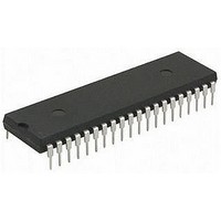
MCU 8BIT 14KB FLASH 5.5V 40PDIP
Manufacturer
Microchip Technology
Series
PIC® XLP™ 16Fr
Specifications of PIC16LF707-I/P
Core Size
8-Bit
Program Memory Size
14KB (8K x 14)
Peripherals
Brown-out Detect/Reset, POR, PWM, WDT
Core Processor
PIC
Speed
20MHz
Connectivity
I²C, SPI, UART/USART
Number Of I /o
36
Program Memory Type
FLASH
Ram Size
363 x 8
Voltage - Supply (vcc/vdd)
1.8 V ~ 3.6 V
Data Converters
A/D 14x8b
Oscillator Type
Internal
Operating Temperature
-40°C ~ 85°C
Package / Case
40-DIP (0.600", 15.24mm)
Controller Family/series
PIC16LF
No. Of I/o's
36
Ram Memory Size
363Byte
Cpu Speed
20MHz
No. Of Timers
6
Processor Series
PIC16LF
Core
PIC
Data Bus Width
8 bit
Data Ram Size
368 B
Interface Type
I2C, SPI, AUSART
Maximum Clock Frequency
20 MHz
Number Of Programmable I/os
36
Number Of Timers
4
Operating Supply Voltage
1.8 V to 3.6 V
Maximum Operating Temperature
+ 85 C
Mounting Style
Through Hole
3rd Party Development Tools
52715-96, 52716-328, 52717-734
Development Tools By Supplier
PG164130, DV164035, DV244005, DV164005, PG164120, ICE2000
Minimum Operating Temperature
- 40 C
On-chip Adc
8 bit, 14 Channel
On-chip Dac
5 bit
Lead Free Status / RoHS Status
Lead free / RoHS Compliant
Eeprom Size
-
Lead Free Status / Rohs Status
Details
Available stocks
Company
Part Number
Manufacturer
Quantity
Price
Company:

Part Number:
PIC16LF707-I/PT
Manufacturer:
Microchip Technology
Quantity:
10 000


PIC16F707/PIC16LF707
REGISTER 8-1:
REGISTER 8-2:
DS41418A-page 76
bit 2-0
Note 1:
bit 15
bit 7
Legend:
R = Readable bit
-n = Value at POR
bit 15-6
bit 5-4
bit 3-0
Note 1:
U-1
U-1
—
—
2:
3:
4:
(1)
(1)
Enabling Brown-out Reset does not automatically enable Power-up Timer.
The entire program memory will be erased when the code protection is turned off.
When MCLR is asserted in INTOSC or RC mode, the internal clock oscillator is disabled.
MPLAB
MPLAB
FOSC<2:0>: Oscillator Selection bits
111 =
110 =
101 =
100 =
011 =
010 =
001 =
000 =
Unimplemented: Read as ‘1’
VCAPEN<1:0>: Voltage Regulator Capacitor Enable bits
For the PIC16LF707:
These bits are ignored. All V
For the PIC16F707:
00 = V
01 = V
10 = V
11 = All V
Unimplemented: Read as ‘1’
®
®
IDE masks unimplemented Configuration bits to ‘0’.
U-1
U-1
IDE masks unimplemented Configuration bits to ‘0’.
—
—
CONFIG1: CONFIGURATION WORD REGISTER 1 (CONTINUED)
CONFIG2: CONFIGURATION WORD REGISTER 2
(1)
(1)
CAP
CAP
CAP
RC oscillator: CLKOUT function on RA6/OSC2/CLKOUT pin, RC on RA7/OSC1/CLKIN
RCIO oscillator: I/O function on RA6/OSC2/CLKOUT pin, RC on RA7/OSC1/CLKIN
INTOSC oscillator: CLKOUT function on RA6/OSC2/CLKOUT pin, I/O function on RA7/OSC1/CLKIN
INTOSCIO oscillator: I/O function on RA6/OSC2/CLKOUT pin, I/O function on RA7/OSC1/CLKIN
EC: I/O function on RA6/OSC2/CLKOUT pin, CLKIN on RA7/OSC1/CLKIN
HS oscillator: High-speed crystal/resonator on RA6/OSC2/CLKOUT and RA7/OSC1/CLKIN
XT oscillator: Crystal/resonator on RA6/OSC2/CLKOUT and RA7/OSC1/CLKIN
LP oscillator: Low-power crystal on RA6/OSC2/CLKOUT and RA7/OSC1/CLKIN
CAP
functionality is enabled on RA0
functionality is enabled on RA5
functionality is enabled on RA6
P = Programmable bit
W = Writable bit
‘1’ = Bit is set
functions are disabled (not recommended)
VCAPEN1
U-1
R/P-1
—
(1)
CAP
VCAPEN0
U-1
R/P-1
pin functions are disabled.
Preliminary
—
(1)
U = Unimplemented bit, read as ‘0’
‘0’ = Bit is cleared
U-1
U-1
—
—
(1)
(1)
U-1
U-1
—
—
(1)
(1)
2010 Microchip Technology Inc.
x = Bit is unknown
U-1
U-1
—
—
(1)
(1)
U-1
U-1
—
—
(1)
(1)
bit 8
bit 0
Related parts for PIC16LF707-I/P
Image
Part Number
Description
Manufacturer
Datasheet
Request
R

Part Number:
Description:
Manufacturer:
Microchip Technology Inc.
Datasheet:
Part Number:
Description:
Manufacturer:
Microchip Technology Inc.
Datasheet:
Part Number:
Description:
Manufacturer:
Microchip Technology Inc.
Datasheet:
Part Number:
Description:
Manufacturer:
Microchip Technology Inc.
Datasheet:
Part Number:
Description:
Manufacturer:
Microchip Technology Inc.
Datasheet:
Part Number:
Description:
Manufacturer:
Microchip Technology Inc.
Datasheet:
Part Number:
Description:
Manufacturer:
Microchip Technology Inc.
Datasheet:
Part Number:
Description:
Manufacturer:
Microchip Technology Inc.
Datasheet: