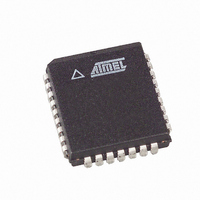
AT89LP828-20JU Atmel, AT89LP828-20JU Datasheet - Page 24

AT89LP828-20JU
Manufacturer Part Number
AT89LP828-20JU
Description
MCU 8051 8K FLASH SPI 32PLCC
Manufacturer
Atmel
Series
89LPr
Datasheet
1.AT89LP428-20AU.pdf
(149 pages)
Specifications of AT89LP828-20JU
Core Processor
8051
Core Size
8-Bit
Speed
20MHz
Connectivity
SPI, UART/USART
Peripherals
Brown-out Detect/Reset, POR, PWM, WDT
Number Of I /o
30
Program Memory Size
8KB (8K x 8)
Program Memory Type
FLASH
Eeprom Size
1K x 8
Ram Size
768 x 8
Voltage - Supply (vcc/vdd)
2.4 V ~ 5.5 V
Oscillator Type
Internal
Operating Temperature
-40°C ~ 85°C
Package / Case
32-PLCC
Processor Series
AT89x
Core
8051
Data Bus Width
8 bit
Data Ram Size
768 B
Interface Type
2-Wire, SPI
Maximum Clock Frequency
20 MHz
Number Of Programmable I/os
30
Number Of Timers
3
Maximum Operating Temperature
+ 85 C
Mounting Style
SMD/SMT
3rd Party Development Tools
PK51, CA51, A51, ULINK2
Development Tools By Supplier
AT89ISP
Minimum Operating Temperature
- 40 C
Lead Free Status / RoHS Status
Lead free / RoHS Compliant
Data Converters
-
Lead Free Status / Rohs Status
Details
Available stocks
Company
Part Number
Manufacturer
Quantity
Price
24
AT89LP428/828
Figure 7-1.
Note:
If the Brown-out Detector (BOD) is also enabled, the start-up timer does not begin counting until
after V
occurs prior to the end of the initialization sequence, the timer must first wait for that sequence to
complete before counting.
The start-up timer delay is user-configurable with the Start-up Time User Fuses and depends on
the clock source
after a Brown-out Reset or when waking up from Power-down during internally timed mode. The
start-up delay should be selected to provide enough settling time for V
source. The device operating environment (supply voltage, frequency, temperature, etc.) must
meet the minimum system requirements before the device exits reset and starts normal opera-
tion. The RST pin may be held low externally until these conditions are met.
Figure 7-2.
Time-out
Time-out
Internal
Internal
Internal
Internal
CC
Reset
Reset
Reset
Reset
RST
RST
t
V
POR
RST
RST
reaches the BOD threshold voltage V
V
CC
CC
is approximately 92 µs ± 5%.
Power-on Reset Sequence (BOD Disabled)
Power-on Reset Sequence (BOD Enabled)
t
POR
(Table
V
POR
7-1). The Start-up Time fuses also control the length of the start-up time
(RST Controlled Externally)
(RST Controlled Externally)
V
V
BOD
POR
t
POR
+ t
SUT
t
SUT
BOD
(RST Tied to V
(RST Tied to V
as shown in
t
RHD
CC
Figure
V
CC
)
V
IH
IH
)
V
POR
t
RHD
7-2. However, if this event
CC
and the selected clock
3654A–MICRO–8/09


