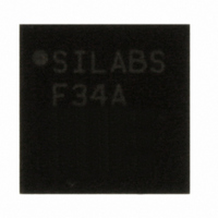
C8051F34A-GM Silicon Laboratories Inc, C8051F34A-GM Datasheet - Page 9

C8051F34A-GM
Manufacturer Part Number
C8051F34A-GM
Description
IC 8051 MCU 64K FLASH MEM 32-QFN
Manufacturer
Silicon Laboratories Inc
Series
C8051F34xr
Datasheet
1.C8051F349-GQ.pdf
(276 pages)
Specifications of C8051F34A-GM
Program Memory Type
FLASH
Program Memory Size
64KB (64K x 8)
Package / Case
32-QFN
Core Processor
8051
Core Size
8-Bit
Speed
48MHz
Connectivity
SMBus (2-Wire/I²C), SPI, UART/USART, USB
Peripherals
Brown-out Detect/Reset, POR, PWM, Temp Sensor, WDT
Number Of I /o
25
Ram Size
4.25K x 8
Voltage - Supply (vcc/vdd)
2.7 V ~ 3.6 V
Data Converters
A/D 17x10b
Oscillator Type
Internal
Operating Temperature
-40°C ~ 85°C
Processor Series
C8051F3x
Core
8051
Data Bus Width
8 bit
Data Ram Size
4352 B
Interface Type
I2C, SPI, UART
Maximum Clock Frequency
25 MHz
Number Of Programmable I/os
25
Number Of Timers
4
Operating Supply Voltage
2.7 V to 5.25 V
Maximum Operating Temperature
+ 85 C
Mounting Style
SMD/SMT
3rd Party Development Tools
KSK-SL-F34X, KSK-SL-TOOLSTICK, PK51, CA51, A51, ULINK2
Development Tools By Supplier
C8051F340DK
Minimum Operating Temperature
- 40 C
On-chip Adc
10 bit
Package
32QFN EP
Device Core
8051
Family Name
C8051F34x
Maximum Speed
48 MHz
Cpu Family
C8051F34x
Device Core Size
8b
Frequency (max)
48MHz
Total Internal Ram Size
4.25KB
# I/os (max)
25
Number Of Timers - General Purpose
4
Operating Supply Voltage (typ)
3.3/5V
Operating Supply Voltage (max)
5.25V
Operating Supply Voltage (min)
2.7V
Instruction Set Architecture
CISC
Operating Temp Range
-40C to 85C
Operating Temperature Classification
Industrial
Mounting
Surface Mount
Pin Count
32
Package Type
QFN EP
Lead Free Status / RoHS Status
Lead free / RoHS Compliant
For Use With
336-1748 - ADAPTER TOOLSTICK FOR C8051F34X
Eeprom Size
-
Lead Free Status / Rohs Status
Lead free / RoHS Compliant
Other names
336-1350-5
12. Flash Memory
13. External Data Memory Interface and On-Chip XRAM
14. Oscillators
15. Port Input/Output
16. Universal Serial Bus Controller (USB0)
17. SMBus
18. UART0
19. UART1 (C8051F340/1/4/5/8/A/B/C Only)
Figure 12.1. Flash Program Memory Map and Security Byte................................. 110
Figure 13.1. USB FIFO Space and XRAM Memory Map
Figure 13.2. Multiplexed Configuration Example.................................................... 119
Figure 13.3. Non-multiplexed Configuration Example ............................................ 120
Figure 13.4. EMIF Operating Modes ...................................................................... 120
Figure 13.5. Non-multiplexed 16-bit MOVX Timing ................................................ 124
Figure 13.6. Non-multiplexed 8-bit MOVX without Bank Select Timing ................. 125
Figure 13.7. Non-multiplexed 8-bit MOVX with Bank Select Timing ...................... 126
Figure 13.8. Multiplexed 16-bit MOVX Timing........................................................ 127
Figure 13.9. Multiplexed 8-bit MOVX without Bank Select Timing ......................... 128
Figure 13.10. Multiplexed 8-bit MOVX with Bank Select Timing ............................ 129
Figure 14.1. Oscillator Diagram.............................................................................. 131
Figure 15.1. Port I/O Functional Block Diagram (Port 0 through Port 3) ................ 142
Figure 15.2. Port I/O Cell Block Diagram ............................................................... 143
Figure 15.3. Peripheral Availability on Port I/O Pins............................................... 144
Figure 15.4. Crossbar Priority Decoder in Example Configuration
Figure 15.5. Crossbar Priority Decoder in
Figure 16.1. USB0 Block Diagram.......................................................................... 159
Figure 16.2. USB0 Register Access Scheme......................................................... 162
Figure 16.3. USB FIFO Allocation .......................................................................... 167
Figure 17.1. SMBus Block Diagram ....................................................................... 188
Figure 17.2. Typical SMBus Configuration ............................................................. 189
Figure 17.3. SMBus Transaction ............................................................................ 190
Figure 17.4. Typical SMBus SCL Generation......................................................... 193
Figure 17.5. Typical Master Transmitter Sequence................................................ 199
Figure 17.6. Typical Master Receiver Sequence.................................................... 200
Figure 17.7. Typical Slave Receiver Sequence...................................................... 201
Figure 17.8. Typical Slave Transmitter Sequence.................................................. 202
Figure 18.1. UART0 Block Diagram ....................................................................... 205
Figure 18.2. UART0 Baud Rate Logic .................................................................... 206
Figure 18.3. UART Interconnect Diagram .............................................................. 207
Figure 18.4. 8-Bit UART Timing Diagram............................................................... 207
Figure 18.5. 9-Bit UART Timing Diagram............................................................... 208
Figure 18.6. UART Multi-Processor Mode Interconnect Diagram .......................... 209
with USBFAE set to ‘1’ ...................................................................................... 115
(No Pins Skipped) ............................................................................................. 145
Example Configuration (3 Pins Skipped) .......................................................... 146
C8051F340/1/2/3/4/5/6/7/8/9/A/B/C/D
Rev. 1.3
9


