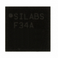
C8051F34A-GM Silicon Laboratories Inc, C8051F34A-GM Datasheet - Page 6

C8051F34A-GM
Manufacturer Part Number
C8051F34A-GM
Description
IC 8051 MCU 64K FLASH MEM 32-QFN
Manufacturer
Silicon Laboratories Inc
Series
C8051F34xr
Datasheet
1.C8051F349-GQ.pdf
(276 pages)
Specifications of C8051F34A-GM
Program Memory Type
FLASH
Program Memory Size
64KB (64K x 8)
Package / Case
32-QFN
Core Processor
8051
Core Size
8-Bit
Speed
48MHz
Connectivity
SMBus (2-Wire/I²C), SPI, UART/USART, USB
Peripherals
Brown-out Detect/Reset, POR, PWM, Temp Sensor, WDT
Number Of I /o
25
Ram Size
4.25K x 8
Voltage - Supply (vcc/vdd)
2.7 V ~ 3.6 V
Data Converters
A/D 17x10b
Oscillator Type
Internal
Operating Temperature
-40°C ~ 85°C
Processor Series
C8051F3x
Core
8051
Data Bus Width
8 bit
Data Ram Size
4352 B
Interface Type
I2C, SPI, UART
Maximum Clock Frequency
25 MHz
Number Of Programmable I/os
25
Number Of Timers
4
Operating Supply Voltage
2.7 V to 5.25 V
Maximum Operating Temperature
+ 85 C
Mounting Style
SMD/SMT
3rd Party Development Tools
KSK-SL-F34X, KSK-SL-TOOLSTICK, PK51, CA51, A51, ULINK2
Development Tools By Supplier
C8051F340DK
Minimum Operating Temperature
- 40 C
On-chip Adc
10 bit
Package
32QFN EP
Device Core
8051
Family Name
C8051F34x
Maximum Speed
48 MHz
Cpu Family
C8051F34x
Device Core Size
8b
Frequency (max)
48MHz
Total Internal Ram Size
4.25KB
# I/os (max)
25
Number Of Timers - General Purpose
4
Operating Supply Voltage (typ)
3.3/5V
Operating Supply Voltage (max)
5.25V
Operating Supply Voltage (min)
2.7V
Instruction Set Architecture
CISC
Operating Temp Range
-40C to 85C
Operating Temperature Classification
Industrial
Mounting
Surface Mount
Pin Count
32
Package Type
QFN EP
Lead Free Status / RoHS Status
Lead free / RoHS Compliant
For Use With
336-1748 - ADAPTER TOOLSTICK FOR C8051F34X
Eeprom Size
-
Lead Free Status / Rohs Status
Lead free / RoHS Compliant
Other names
336-1350-5
C8051F340/1/2/3/4/5/6/7/8/9/A/B/C/D
18. UART0.................................................................................................................... 205
19. UART1 (C8051F340/1/4/5/8/A/B/C Only).............................................................. 213
20. Enhanced Serial Peripheral Interface (SPI0)...................................................... 222
21. Timers.................................................................................................................... 235
22. Programmable Counter Array (PCA0) ................................................................ 255
6
17.6.SMBus Status Decoding................................................................................. 202
18.1.Enhanced Baud Rate Generation................................................................... 206
18.2.Operational Modes ......................................................................................... 206
18.3.Multiprocessor Communications .................................................................... 208
19.1.Baud Rate Generator ..................................................................................... 214
19.2.Data Format.................................................................................................... 215
19.3.Configuration and Operation .......................................................................... 216
20.1.Signal Descriptions......................................................................................... 223
20.2.SPI0 Master Mode Operation ......................................................................... 224
20.3.SPI0 Slave Mode Operation ........................................................................... 226
20.4.SPI0 Interrupt Sources ................................................................................... 226
20.5.Serial Clock Timing......................................................................................... 227
20.6.SPI Special Function Registers ...................................................................... 229
21.1.Timer 0 and Timer 1 ....................................................................................... 235
21.2.Timer 2 .......................................................................................................... 243
21.3.Timer 3 .......................................................................................................... 249
22.1.PCA Counter/Timer ........................................................................................ 256
22.2.Capture/Compare Modules ............................................................................ 257
17.5.3.Slave Receiver Mode ............................................................................. 201
17.5.4.Slave Transmitter Mode ......................................................................... 202
18.2.1.8-Bit UART ............................................................................................. 207
18.2.2.9-Bit UART ............................................................................................. 208
19.3.1.Data Transmission ................................................................................. 216
19.3.2.Data Reception ...................................................................................... 216
19.3.3.Multiprocessor Communications ............................................................ 217
20.1.1.Master Out, Slave In (MOSI).................................................................. 223
20.1.2.Master In, Slave Out (MISO).................................................................. 223
20.1.3.Serial Clock (SCK) ................................................................................. 223
20.1.4.Slave Select (NSS) ................................................................................ 223
21.1.1.Mode 0: 13-bit Counter/Timer ................................................................ 235
21.1.2.Mode 1: 16-bit Counter/Timer ................................................................ 236
21.1.3.Mode 2: 8-bit Counter/Timer with Auto-Reload...................................... 237
21.1.4.Mode 3: Two 8-bit Counter/Timers (Timer 0 Only)................................. 238
21.2.1.16-bit Timer with Auto-Reload................................................................ 243
21.2.2.8-bit Timers with Auto-Reload................................................................ 244
21.2.3.Timer 2 Capture Modes: USB Start-of-Frame or LFO Falling Edge ...... 245
21.3.1.16-bit Timer with Auto-Reload................................................................ 249
21.3.2.8-bit Timers with Auto-Reload................................................................ 250
21.3.3.USB Start-of-Frame Capture.................................................................. 251
22.2.1.Edge-triggered Capture Mode................................................................ 258
Rev. 1.3


