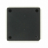
MB91F479PMC1-GE1 Fujitsu Semiconductor America Inc, MB91F479PMC1-GE1 Datasheet - Page 27

MB91F479PMC1-GE1
Manufacturer Part Number
MB91F479PMC1-GE1
Description
IC MCU 512KB FLASH 144-LQFP
Manufacturer
Fujitsu Semiconductor America Inc
Series
FR MB91470r
Datasheet
1.MB91F482PMC-GE1.pdf
(96 pages)
Specifications of MB91F479PMC1-GE1
Core Processor
FR60 RISC
Core Size
32-Bit
Speed
80MHz
Connectivity
EBI/EMI, I²C, FIFO, SIO
Peripherals
DMA, PWM, WDT
Number Of I /o
113
Program Memory Size
512KB (512K x 8)
Program Memory Type
FLASH
Ram Size
32K x 8
Voltage - Supply (vcc/vdd)
4 V ~ 5.5 V
Data Converters
A/D 12x8/10b, 4x12b
Oscillator Type
External
Operating Temperature
-40°C ~ 85°C
Package / Case
144-LQFP
For Use With
865-1109 - KIT 32BIT RSC MCU MOTOR CONTROL
Lead Free Status / RoHS Status
Lead free / RoHS Compliant
Eeprom Size
-
Other names
865-1095
Available stocks
Company
Part Number
Manufacturer
Quantity
Price
Company:
Part Number:
MB91F479PMC1-GE1
Manufacturer:
Fujitsu Semiconductor America Inc
Quantity:
10 000
• Order of power turning ON/OFF
• Source oscillation input when turning on the power
• Cautions for operation during PLL clock mode
• Using an external clock
• C pin
• Software reset on the synchronous mode
• Example of Using an External Clock
Use the following procedure for turning the power on or off. If not using the A/D converter, connect AV
and AV
the reverse sequence.
When turning the power on, maintain the clock input until the device is released from the oscillation stabilization
wait state.
Even if the oscillator comes off or the clock input stops with the PLL clock selected for MB91470/480 series,
MB91470/480 series may continue to operate at the free-run frequency of the PLL’s internal self-oscillating
oscillator circuit.
Performance of this operation, however, cannot be guaranteed.
When using an external clock, you must always input clock signals with opposite phase from X0 pin to X1 pin
simultaneously. However, as the X1 pin halts with an output at the "H" level during stop mode, insert a resistor
of approximately 1 kΩ externally to prevent a conflict between the two outputs if using stop mode (oscillation
stop mode).
The figure below shows an example of how to use an external clock.
As MB91470/480 series includes an internal regulator, always connect a bypass capacitor of approximately
4.7 µF to the C pin for use by the regulator.
Be sure to meet the following two conditions before setting 0 to the SRST bit of STCR (standby control register)
when the software reset is used on the synchronous mode.
• Set the interrupt enable flag (I-Flag) to interrupts disabled (I-Flag=0).
• Not used NMI
SS
= V
SS
. Turn on the power supply in the sequence V
MB91470/480
series
VSS
C
CC
X0
X1
GND
→ AV
MB91470/480
MB91470/480 Series
4.7 µF
CC
series
→ AVRH, and turn off the power in
CC
=V
CC
27


