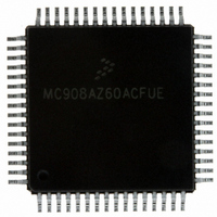
MC908AZ60ACFUE Freescale Semiconductor, MC908AZ60ACFUE Datasheet - Page 89

MC908AZ60ACFUE
Manufacturer Part Number
MC908AZ60ACFUE
Description
IC MCU FLASH 8.4MHZ 60K 64QFP
Manufacturer
Freescale Semiconductor
Series
HC08r
Datasheet
1.MC908AZ60ACFUER.pdf
(414 pages)
Specifications of MC908AZ60ACFUE
Core Processor
HC08
Core Size
8-Bit
Speed
8.4MHz
Connectivity
CAN, SCI, SPI
Peripherals
LVD, POR, PWM
Number Of I /o
52
Program Memory Size
60KB (60K x 8)
Program Memory Type
FLASH
Eeprom Size
1K x 8
Ram Size
2K x 8
Voltage - Supply (vcc/vdd)
4.5 V ~ 5.5 V
Data Converters
A/D 15x8b
Oscillator Type
Internal
Operating Temperature
-40°C ~ 85°C
Package / Case
64-QFP
Lead Free Status / RoHS Status
Lead free / RoHS Compliant
Available stocks
Company
Part Number
Manufacturer
Quantity
Price
Company:
Part Number:
MC908AZ60ACFUE
Manufacturer:
Freescale Semiconductor
Quantity:
10 000
Part Number:
MC908AZ60ACFUE
Manufacturer:
FREESCALE
Quantity:
20 000
Company:
Part Number:
MC908AZ60ACFUE1L87J
Manufacturer:
TEMIC
Quantity:
350
Company:
Part Number:
MC908AZ60ACFUER
Manufacturer:
FREESCALE
Quantity:
5 560
Company:
Part Number:
MC908AZ60ACFUER
Manufacturer:
Freescale Semiconductor
Quantity:
10 000
- Current page: 89 of 414
- Download datasheet (5Mb)
7.4.5 EEPROM-2 Programming and Erasing
The unprogrammed or erase state of an EEPROM bit is a logic 1. The factory default for all bytes within
the EEPROM-2 array is $FF.
The programming operation changes an EEPROM bit from logic 1 to logic 0 (programming cannot change
a bit from logic 0 to a logic 1). In a single programming operation, the minimum EEPROM programming
size is one bit; the maximum is eight bits (one byte).
The erase operation changes an EEPROM bit from logic 0 to logic 1. In a single erase operation, the
minimum EEPROM erase size is one byte; the maximum is the entire EEPROM-2 array.
The EEPROM can be programmed such that one or multiple bits are programmed (written to a logic 0) at
a time. However, the user may never program the same bit location more than once before erasing the
entire byte. In other words, the user is not allowed to program a logic 0 to a bit that is already programmed
(bit state is already logic 0).
For some applications it might be advantageous to track more than 10K events with a single byte of
EEPROM by programming one bit at a time. For that purpose, a special selective bit programming
technique is available. An example of this technique is illustrated in
When this technique is utilized, a program/erase cycle is defined as multiple program sequences (up to
eight) to a unique location followed by a single erase operation.
7.4.5.1 Program/Erase Using AUTO Bit
An additional feature available for EEPROM-2 program and erase operations is the AUTO mode. When
enabled, AUTO mode will activate an internal timer that will automatically terminate the program/erase
cycle and clear the EEPGM bit. Please see
Erasing, and
Freescale Semiconductor
Original state of byte (erased)
First event is recorded by programming bit position 0
Second event is recorded by programming bit position 1
Third event is recorded by programming bit position 2
Fourth event is recorded by programming bit position 3
Events five through eight are recorded in a similar fashion
7.5.1 EEPROM-2 Control Register
None of the bit locations are actually programmed more than once although
the byte was programmed eight times.
MC68HC908AZ60A • MC68HC908AS60A • MC68HC908AS60E Data Sheet, Rev. 6
Table 7-2. Example Selective Bit Programming Description
Description
7.4.5.2 EEPROM-2
for more information.
NOTE
Programming,
Program Data
Table
1111:1110
1111:1101
1111:1011
1111:0111
in Binary
n/a
7-2.
7.4.5.3 EEPROM-2
1111:1111
1111:1110
1111:1100
1111:1000
1111:0000
Functional Description
in Binary
Result
89
Related parts for MC908AZ60ACFUE
Image
Part Number
Description
Manufacturer
Datasheet
Request
R
Part Number:
Description:
Manufacturer:
Freescale Semiconductor, Inc
Datasheet:
Part Number:
Description:
Manufacturer:
Freescale Semiconductor, Inc
Datasheet:
Part Number:
Description:
Manufacturer:
Freescale Semiconductor, Inc
Datasheet:
Part Number:
Description:
Manufacturer:
Freescale Semiconductor, Inc
Datasheet:
Part Number:
Description:
Manufacturer:
Freescale Semiconductor, Inc
Datasheet:
Part Number:
Description:
Manufacturer:
Freescale Semiconductor, Inc
Datasheet:
Part Number:
Description:
Manufacturer:
Freescale Semiconductor, Inc
Datasheet:
Part Number:
Description:
Manufacturer:
Freescale Semiconductor, Inc
Datasheet:
Part Number:
Description:
Manufacturer:
Freescale Semiconductor, Inc
Datasheet:
Part Number:
Description:
Manufacturer:
Freescale Semiconductor, Inc
Datasheet:
Part Number:
Description:
Manufacturer:
Freescale Semiconductor, Inc
Datasheet:
Part Number:
Description:
Manufacturer:
Freescale Semiconductor, Inc
Datasheet:
Part Number:
Description:
Manufacturer:
Freescale Semiconductor, Inc
Datasheet:
Part Number:
Description:
Manufacturer:
Freescale Semiconductor, Inc
Datasheet:
Part Number:
Description:
Manufacturer:
Freescale Semiconductor, Inc
Datasheet:


