MC9S12C32CFAE25 Freescale Semiconductor, MC9S12C32CFAE25 Datasheet - Page 216
MC9S12C32CFAE25
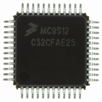
Manufacturer Part Number
MC9S12C32CFAE25
Description
IC MCU 32K FLASH 25MHZ 48-LQFP
Manufacturer
Freescale Semiconductor
Series
HCS12r
Datasheets
1.MC9S12GC16MFUE.pdf
(690 pages)
2.MC9S12C96CFUER.pdf
(26 pages)
3.MC9S12C32CFAE25.pdf
(2 pages)
4.MC9S12C32CPBE25.pdf
(36 pages)
Specifications of MC9S12C32CFAE25
Core Processor
HCS12
Core Size
16-Bit
Speed
25MHz
Connectivity
CAN, EBI/EMI, SCI, SPI
Peripherals
POR, PWM, WDT
Number Of I /o
31
Program Memory Size
32KB (32K x 8)
Program Memory Type
FLASH
Ram Size
2K x 8
Voltage - Supply (vcc/vdd)
2.35 V ~ 5.5 V
Data Converters
A/D 8x10b
Oscillator Type
Internal
Operating Temperature
-40°C ~ 85°C
Package / Case
48-LQFP
Processor Series
S12C
Core
HCS12
Data Bus Width
16 bit
Data Ram Size
2 KB
Interface Type
CAN/SCI/SPI
Maximum Clock Frequency
25 MHz
Number Of Programmable I/os
31
Number Of Timers
8
Maximum Operating Temperature
+ 85 C
Mounting Style
SMD/SMT
3rd Party Development Tools
EWHCS12
Development Tools By Supplier
M68EVB912C32EE
Minimum Operating Temperature
- 40 C
On-chip Adc
8-ch x 10-bit
For Use With
CML12C32SLK - KIT STUDENT LEARNING 16BIT HCS12
Lead Free Status / RoHS Status
Lead free / RoHS Compliant
Eeprom Size
-
Lead Free Status / Rohs Status
Lead free / RoHS Compliant
Available stocks
Company
Part Number
Manufacturer
Quantity
Price
Company:

Part Number:
MC9S12C32CFAE25
Manufacturer:
FREESCAL
Quantity:
240
Company:
Part Number:
MC9S12C32CFAE25
Manufacturer:
Freescale Semiconductor
Quantity:
10 000


Chapter 7 Debug Module (DBGV1) Block Description
7.4.2.3
The definitions of begin- and end-trigger as used in the DBG module are as follows:
7.4.2.4
In DBG mode, arming occurs by setting DBGEN and ARM in DBGC1. The ARM bit in DBGC1 is cleared
when the trigger condition is met in end-trigger mode or when the Trace Buffer is filled in begin-trigger
mode. The TBC logic determines whether a trigger condition has been met based on the trigger mode and
the trigger selection.
7.4.2.5
The DBG module supports nine trigger modes. The trigger modes are encoded as shown in
trigger mode is used as a qualifier for either starting or ending the storing of data in the trace buffer. When
the match condition is met, the appropriate flag A or B is set in DBGSC. Arming the DBG module clears
the A, B, and C flags in DBGSC. In all trigger modes except for the event-only modes and DETAIL capture
mode, change-of-flow addresses are stored in the trace buffer. In the event-only modes only the value on
the data bus at the trigger event B will be stored. In DETAIL capture mode address and data for all cycles
except program fetch (P) and free (f) cycles are stored in trace buffer.
7.4.2.5.1
In the A only trigger mode, if the match condition for A is met, the A flag in DBGSC is set and a trigger
occurs.
7.4.2.5.2
In the A or B trigger mode, if the match condition for A or B is met, the corresponding flag in DBGSC is
set and a trigger occurs.
7.4.2.5.3
In the A then B trigger mode, the match condition for A must be met before the match condition for B is
compared. When the match condition for A or B is met, the corresponding flag in DBGSC is set. The
trigger occurs only after A then B have matched.
216
•
•
Begin-trigger: Storage in trace buffer occurs after the trigger and continues until 64 locations are
filled.
End-trigger: Storage in trace buffer occurs until the trigger, with the least recent data falling out of
the trace buffer if more than 64 words are collected.
Begin- and End-Trigger
Arming the DBG Module
Trigger Modes
A Only
A or B
A then B
When tagging and using A then B, if addresses A and B are close together,
then B may not complete the trigger sequence. This occurs when A and B
are in the instruction queue at the same time. Basically the A trigger has not
yet occurred, so the B instruction is not tagged. Generally, if address B is at
MC9S12C-Family / MC9S12GC-Family
Rev 01.24
NOTE
Freescale Semiconductor
Table
7-6. The
Related parts for MC9S12C32CFAE25
Image
Part Number
Description
Manufacturer
Datasheet
Request
R

Part Number:
Description:
Manufacturer:
Freescale Semiconductor, Inc
Datasheet:
Part Number:
Description:
Manufacturer:
Freescale Semiconductor, Inc
Datasheet:
Part Number:
Description:
Manufacturer:
Freescale Semiconductor, Inc
Datasheet:
Part Number:
Description:
Manufacturer:
Freescale Semiconductor, Inc
Datasheet:
Part Number:
Description:
Manufacturer:
Freescale Semiconductor, Inc
Datasheet:
Part Number:
Description:
Manufacturer:
Freescale Semiconductor, Inc
Datasheet:
Part Number:
Description:
Manufacturer:
Freescale Semiconductor, Inc
Datasheet:
Part Number:
Description:
Manufacturer:
Freescale Semiconductor, Inc
Datasheet:
Part Number:
Description:
Manufacturer:
Freescale Semiconductor, Inc
Datasheet:
Part Number:
Description:
Manufacturer:
Freescale Semiconductor, Inc
Datasheet:
Part Number:
Description:
Manufacturer:
Freescale Semiconductor, Inc
Datasheet:
Part Number:
Description:
Manufacturer:
Freescale Semiconductor, Inc
Datasheet:
Part Number:
Description:
Manufacturer:
Freescale Semiconductor, Inc
Datasheet:
Part Number:
Description:
Manufacturer:
Freescale Semiconductor, Inc
Datasheet:
Part Number:
Description:
Manufacturer:
Freescale Semiconductor, Inc
Datasheet: