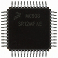
MC908SR12MFAE Freescale Semiconductor, MC908SR12MFAE Datasheet - Page 298

MC908SR12MFAE
Manufacturer Part Number
MC908SR12MFAE
Description
IC MCU 12K FLASH 8MHZ 48-LQFP
Manufacturer
Freescale Semiconductor
Series
HC08r
Datasheet
1.MC908SR12MFAE.pdf
(404 pages)
Specifications of MC908SR12MFAE
Core Processor
HC08
Core Size
8-Bit
Speed
8MHz
Connectivity
I²C, SCI
Peripherals
LVD, POR, PWM, Temp Sensor
Number Of I /o
31
Program Memory Size
12KB (12K x 8)
Program Memory Type
FLASH
Ram Size
512 x 8
Voltage - Supply (vcc/vdd)
4.5 V ~ 5.5 V
Data Converters
A/D 14x10b
Oscillator Type
Internal
Operating Temperature
-40°C ~ 125°C
Package / Case
48-LQFP
Lead Free Status / RoHS Status
Lead free / RoHS Compliant
Eeprom Size
-
Available stocks
Company
Part Number
Manufacturer
Quantity
Price
Company:
Part Number:
MC908SR12MFAE
Manufacturer:
Freescale Semiconductor
Quantity:
10 000
Company:
Part Number:
MC908SR12MFAER
Manufacturer:
Freescale Semiconductor
Quantity:
10 000
- Current page: 298 of 404
- Download datasheet (2Mb)
Multi-Master IIC Interface (MMIIC)
17.6.7 Clock Synchronization
17.6.8 Handshaking
Data Sheet
298
Since wired-AND logic is performed on SCL line, a high to low transition
on the SCL line will affect the devices connected to the bus. The devices
start counting their low period once a device’s clock has gone low, it will
hold the SCL line low until the clock high state is reached. However, the
change of low to high in this device clock may not change the state of the
SCL line if another device clock is still in its low period. Therefore the
synchronized clock SCL will be held low by the device which last
releases SCL to logic high. Devices with shorter low periods enter a high
wait state during this time. When all devices concerned have counted off
their low period, the synchronized SCL line will be released and go high,
and all devices will start counting their high periods. The first device to
complete its high period will again pull the SCL line low.
illustrates the clock synchronization waveforms.
The clock synchronization mechanism can be used as a handshake in
data transfer. A slave device may hold the SCL low after completion of
one byte data transfer and will halt the bus clock, forcing the master
clock into a wait state until the slave releases the SCL line.
Multi-Master IIC Interface (MMIIC)
SCL1
SCL2
SCL
Figure 17-3. Clock Synchronization
Internal counter reset
MC68HC908SR12•MC68HC08SR12 — Rev. 5.0
WAIT
Start counting high period
Freescale Semiconductor
Figure 17-3
Related parts for MC908SR12MFAE
Image
Part Number
Description
Manufacturer
Datasheet
Request
R
Part Number:
Description:
Manufacturer:
Freescale Semiconductor, Inc
Datasheet:
Part Number:
Description:
Manufacturer:
Freescale Semiconductor, Inc
Datasheet:
Part Number:
Description:
Manufacturer:
Freescale Semiconductor, Inc
Datasheet:
Part Number:
Description:
Manufacturer:
Freescale Semiconductor, Inc
Datasheet:
Part Number:
Description:
Manufacturer:
Freescale Semiconductor, Inc
Datasheet:
Part Number:
Description:
Manufacturer:
Freescale Semiconductor, Inc
Datasheet:
Part Number:
Description:
Manufacturer:
Freescale Semiconductor, Inc
Datasheet:
Part Number:
Description:
Manufacturer:
Freescale Semiconductor, Inc
Datasheet:
Part Number:
Description:
Manufacturer:
Freescale Semiconductor, Inc
Datasheet:
Part Number:
Description:
Manufacturer:
Freescale Semiconductor, Inc
Datasheet:
Part Number:
Description:
Manufacturer:
Freescale Semiconductor, Inc
Datasheet:
Part Number:
Description:
Manufacturer:
Freescale Semiconductor, Inc
Datasheet:
Part Number:
Description:
Manufacturer:
Freescale Semiconductor, Inc
Datasheet:
Part Number:
Description:
Manufacturer:
Freescale Semiconductor, Inc
Datasheet:
Part Number:
Description:
Manufacturer:
Freescale Semiconductor, Inc
Datasheet:


