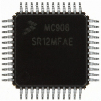
MC908SR12MFAE Freescale Semiconductor, MC908SR12MFAE Datasheet - Page 238

MC908SR12MFAE
Manufacturer Part Number
MC908SR12MFAE
Description
IC MCU 12K FLASH 8MHZ 48-LQFP
Manufacturer
Freescale Semiconductor
Series
HC08r
Datasheet
1.MC908SR12MFAE.pdf
(404 pages)
Specifications of MC908SR12MFAE
Core Processor
HC08
Core Size
8-Bit
Speed
8MHz
Connectivity
I²C, SCI
Peripherals
LVD, POR, PWM, Temp Sensor
Number Of I /o
31
Program Memory Size
12KB (12K x 8)
Program Memory Type
FLASH
Ram Size
512 x 8
Voltage - Supply (vcc/vdd)
4.5 V ~ 5.5 V
Data Converters
A/D 14x10b
Oscillator Type
Internal
Operating Temperature
-40°C ~ 125°C
Package / Case
48-LQFP
Lead Free Status / RoHS Status
Lead free / RoHS Compliant
Eeprom Size
-
Available stocks
Company
Part Number
Manufacturer
Quantity
Price
Company:
Part Number:
MC908SR12MFAE
Manufacturer:
Freescale Semiconductor
Quantity:
10 000
Company:
Part Number:
MC908SR12MFAER
Manufacturer:
Freescale Semiconductor
Quantity:
10 000
- Current page: 238 of 404
- Download datasheet (2Mb)
Analog-to-Digital Converter (ADC)
15.4.6 Result Justification
Data Sheet
238
The conversion result may be formatted in four different ways.
All four of these modes are controlled using MODE0 and MODE1 bits
located in the ADC clock control register (ADICLK).
Left justification will place the eight most significant bits (MSB) in the
corresponding ADC data register high (ADRH). This may be useful if the
result is to be treated as an 8-bit result where the least significant two
bits, located in the ADC data register low (ADRL) can be ignored.
However, you must read ADRL after ADRH or else the interlocking will
prevent all new conversions from being stored.
Right justification will place only the two MSBs in the corresponding ADC
data register high (ADRH) and the eight LSB bits in ADC data register
low (ADRL). This mode of operation typically is used when a 10-bit
unsigned result is desired.
Left justified sign data mode is similar to left justified mode with one
exception. The MSB of the 10-bit result, AD9 located in ADRH is
complemented. This mode of operation is useful when a result,
represented as a signed magnitude from mid-scale, is needed.
Finally, 8-bit truncation mode will place the eight MSBs in ADC data
register low (ADRL). The two LSBs are dropped. This mode of operation
is used when compatibility with 8-bit ADC designs are required. No
interlocking between ADRH and ADRL is present.
•
•
•
•
Left justified
Right justified
Left justified sign data mode
8-bit truncation
Analog-to-Digital Converter (ADC)
MC68HC908SR12•MC68HC08SR12 — Rev. 5.0
Freescale Semiconductor
Related parts for MC908SR12MFAE
Image
Part Number
Description
Manufacturer
Datasheet
Request
R
Part Number:
Description:
Manufacturer:
Freescale Semiconductor, Inc
Datasheet:
Part Number:
Description:
Manufacturer:
Freescale Semiconductor, Inc
Datasheet:
Part Number:
Description:
Manufacturer:
Freescale Semiconductor, Inc
Datasheet:
Part Number:
Description:
Manufacturer:
Freescale Semiconductor, Inc
Datasheet:
Part Number:
Description:
Manufacturer:
Freescale Semiconductor, Inc
Datasheet:
Part Number:
Description:
Manufacturer:
Freescale Semiconductor, Inc
Datasheet:
Part Number:
Description:
Manufacturer:
Freescale Semiconductor, Inc
Datasheet:
Part Number:
Description:
Manufacturer:
Freescale Semiconductor, Inc
Datasheet:
Part Number:
Description:
Manufacturer:
Freescale Semiconductor, Inc
Datasheet:
Part Number:
Description:
Manufacturer:
Freescale Semiconductor, Inc
Datasheet:
Part Number:
Description:
Manufacturer:
Freescale Semiconductor, Inc
Datasheet:
Part Number:
Description:
Manufacturer:
Freescale Semiconductor, Inc
Datasheet:
Part Number:
Description:
Manufacturer:
Freescale Semiconductor, Inc
Datasheet:
Part Number:
Description:
Manufacturer:
Freescale Semiconductor, Inc
Datasheet:
Part Number:
Description:
Manufacturer:
Freescale Semiconductor, Inc
Datasheet:


