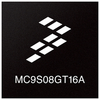
MC9S08GT16AMFDE Freescale Semiconductor, MC9S08GT16AMFDE Datasheet - Page 235

MC9S08GT16AMFDE
Manufacturer Part Number
MC9S08GT16AMFDE
Description
IC MCU 16K FLASH 2K RAM 48-QFN
Manufacturer
Freescale Semiconductor
Series
HCS08r
Datasheet
1.MC9S08GT8ACFBER.pdf
(300 pages)
Specifications of MC9S08GT16AMFDE
Core Processor
HCS08
Core Size
8-Bit
Speed
40MHz
Connectivity
I²C, SCI, SPI
Peripherals
LVD, POR, PWM, WDT
Number Of I /o
39
Program Memory Size
16KB (16K x 8)
Program Memory Type
FLASH
Ram Size
2K x 8
Voltage - Supply (vcc/vdd)
1.8 V ~ 3.6 V
Data Converters
A/D 8x10b
Oscillator Type
Internal
Operating Temperature
-40°C ~ 125°C
Package / Case
48-QFN
Processor Series
S08GT
Core
HCS08
Data Bus Width
8 bit
Data Ram Size
2 KB
Interface Type
I2C, IRSCI, SPI
Maximum Clock Frequency
20 MHz
Number Of Programmable I/os
39
Operating Supply Voltage
3.6 V
Maximum Operating Temperature
+ 125 C
Mounting Style
SMD/SMT
3rd Party Development Tools
EWS08
Development Tools By Supplier
M68EVB908GB60E, M68DEMO908GB60E
Minimum Operating Temperature
- 40 C
On-chip Adc
10 bit
Package
48QFN EP
Family Name
HCS08
Maximum Speed
40 MHz
For Use With
M68DEMO908GB60E - BOARD DEMO MC9S08GB60M68EVB908GB60E - BOARD EVAL FOR MC9S08GB60
Lead Free Status / RoHS Status
Lead free / RoHS Compliant
Eeprom Size
-
Lead Free Status / Rohs Status
Lead free / RoHS Compliant
- Current page: 235 of 300
- Download datasheet (2Mb)
14.5
The ATD module is reset on system reset. If the system reset signal is activated, the ATD registers are
initialized back to their reset state and the ATD module is powered down. This occurs as a function of the
register file initialization; the reset definition of the ATDPU bit (power down bit) is zero or disabled.
The MCU places the module back into an initialized state. If the module is performing a conversion, the
current conversion is terminated, the conversion complete flag is cleared, and the SAR register bits are
cleared. Any pending interrupts are also cancelled. Note that the control, test, and status registers are
initialized on reset; the initialized register state is defined in the register description section of this
specification.
Enabling the module (using the ATDPU bit) does not cause the module to reset since the register file is not
initialized. Finally, writing to control register ATDC does not cause the module to reset; the current
conversion will be terminated.
14.6
The ATD module originates interrupt requests and the MCU handles or services these requests. Details on
how the ATD interrupt requests are handled can be found in the resets and interrupts chapter of this data
sheet.
The ATD interrupt function is enabled by setting the ATDIE bit in the ATDSC register. When the ATDIE
bit is set, an interrupt is generated at the end of an ATD conversion and the ATD result registers (ATDRH
and ATDRL) contain the result data generated by the conversion. If the interrupt function is disabled
(ATDIE = 0), then the CCF flag must be polled to determine when a conversion is complete.
The interrupt will remain pending as long as the CCF flag is set. The CCF bit is cleared whenever the ATD
status and control (ATDSC) register is written. The CCF bit is also cleared whenever the ATD result
registers (ATDRH or ATDRL) are read.
Freescale Semiconductor
Resets
Interrupts
Interrupt
CCF
Enable
MC9S08GT16A/GT8A Data Sheet, Rev. 1
ATDIE
Local
Table 14-8. Interrupt Summary
Conversion complete
Description
Analog-to-Digital Converter (S08ATDV3)
235
Related parts for MC9S08GT16AMFDE
Image
Part Number
Description
Manufacturer
Datasheet
Request
R
Part Number:
Description:
Manufacturer:
Freescale Semiconductor, Inc
Datasheet:
Part Number:
Description:
Manufacturer:
Freescale Semiconductor, Inc
Datasheet:
Part Number:
Description:
Manufacturer:
Freescale Semiconductor, Inc
Datasheet:
Part Number:
Description:
Manufacturer:
Freescale Semiconductor, Inc
Datasheet:
Part Number:
Description:
Manufacturer:
Freescale Semiconductor, Inc
Datasheet:
Part Number:
Description:
Manufacturer:
Freescale Semiconductor, Inc
Datasheet:
Part Number:
Description:
Manufacturer:
Freescale Semiconductor, Inc
Datasheet:
Part Number:
Description:
Manufacturer:
Freescale Semiconductor, Inc
Datasheet:
Part Number:
Description:
Manufacturer:
Freescale Semiconductor, Inc
Datasheet:
Part Number:
Description:
Manufacturer:
Freescale Semiconductor, Inc
Datasheet:
Part Number:
Description:
Manufacturer:
Freescale Semiconductor, Inc
Datasheet:
Part Number:
Description:
Manufacturer:
Freescale Semiconductor, Inc
Datasheet:
Part Number:
Description:
Manufacturer:
Freescale Semiconductor, Inc
Datasheet:
Part Number:
Description:
Manufacturer:
Freescale Semiconductor, Inc
Datasheet:
Part Number:
Description:
Manufacturer:
Freescale Semiconductor, Inc
Datasheet:


