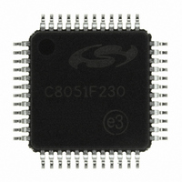
C8051F230-GQ Silicon Laboratories Inc, C8051F230-GQ Datasheet - Page 8

C8051F230-GQ
Manufacturer Part Number
C8051F230-GQ
Description
IC 8051 MCU 8K FLASH 48TQFP
Manufacturer
Silicon Laboratories Inc
Series
C8051F2xxr
Specifications of C8051F230-GQ
Program Memory Type
FLASH
Program Memory Size
8KB (8K x 8)
Package / Case
48-TQFP, 48-VQFP
Core Processor
8051
Core Size
8-Bit
Speed
25MHz
Connectivity
SPI, UART/USART
Peripherals
Brown-out Detect/Reset, POR, WDT
Number Of I /o
32
Ram Size
256 x 8
Voltage - Supply (vcc/vdd)
2.7 V ~ 3.6 V
Oscillator Type
Internal
Operating Temperature
-40°C ~ 85°C
Processor Series
C8051F2x
Core
8051
Data Bus Width
8 bit
Data Ram Size
256 B
Interface Type
SPI/UART
Maximum Clock Frequency
25 MHz
Number Of Programmable I/os
32
Number Of Timers
3
Operating Supply Voltage
2.7 V to 3.6 V
Maximum Operating Temperature
+ 85 C
Mounting Style
SMD/SMT
3rd Party Development Tools
PK51, CA51, A51, ULINK2
Development Tools By Supplier
C8051F226DK
Minimum Operating Temperature
- 40 C
No. Of I/o's
32
Ram Memory Size
256Byte
Cpu Speed
25MHz
No. Of Timers
3
Rohs Compliant
Yes
Package
48TQFP
Device Core
8051
Family Name
C8051F2xx
Maximum Speed
25 MHz
Lead Free Status / RoHS Status
Lead free / RoHS Compliant
Eeprom Size
-
Data Converters
-
Lead Free Status / Rohs Status
Lead free / RoHS Compliant
Other names
336-1242
Available stocks
Company
Part Number
Manufacturer
Quantity
Price
Company:
Part Number:
C8051F230-GQ
Manufacturer:
SiliconL
Quantity:
138
Company:
Part Number:
C8051F230-GQ
Manufacturer:
Silicon Laboratories Inc
Quantity:
10 000
Company:
Part Number:
C8051F230-GQR
Manufacturer:
Silicon Laboratories Inc
Quantity:
10 000
C8051F2xx
10. Flash Memory
11. On-Chip XRAM (C8051F206/226/236)
12. Reset Sources
13. Oscillator
14. Port Input/Output
15. Serial Peripheral Interface Bus
16. UART
17. Timers
18. JTAG
8
Table 9.1. CIP-51 Instruction Set Summary............................................................ 60
Figure 9.2. Memory Map .......................................................................................... 66
Table 9.2. Special Function Register Memory Map ................................................ 68
Table 9.3. Special Function Registers .................................................................... 69
Table 9.4. Interrupt Summary ................................................................................. 75
Table 10.1. Flash Memory Electrical Characteristics ............................................... 86
Figure 10.1. Flash Program Memory Security Bytes................................................ 87
Figure 12.1. Reset Sources Diagram ....................................................................... 91
Figure 12.2. VDD Monitor Timing Diagram .............................................................. 92
Table 12.1. VDD Monitor Electrical Characteristics.................................................. 96
Figure 13.1. Oscillator Diagram................................................................................ 97
Table 13.1. Internal Oscillator Electrical Characteristics .......................................... 98
Figure 14.1. Port I/O Functional Block Diagram ..................................................... 102
Figure 14.2. Port I/O Cell Block Diagram ............................................................... 102
Table 14.1. Port I/O DC Electrical Characteristics.................................................. 109
Figure 15.1. SPI Block Diagram ............................................................................. 110
Figure 15.2. SPI Block Diagram ............................................................................. 111
Figure 15.3. Full Duplex Operation......................................................................... 112
Figure 15.4. Full Duplex Operation......................................................................... 113
Figure 16.1. UART Block Diagram ......................................................................... 117
Table 16.1. UART Modes ....................................................................................... 118
Figure 16.2. UART Mode 0 Interconnect................................................................ 118
Figure 16.3. UART Mode 0 Timing Diagram .......................................................... 118
Figure 16.4. UART Mode 1 Timing Diagram .......................................................... 119
Figure 16.5. UART Modes 1, 2, and 3 Interconnect Diagram ................................ 120
Figure 16.6. UART Modes 2 and 3 Timing Diagram .............................................. 121
Figure 16.7. UART Multi-Processor Mode Interconnect Diagram .......................... 122
Table 16.2. Oscillator Frequencies for Standard Baud Rates ................................ 122
Figure 17.1. T0 Mode 0 Block Diagram.................................................................. 126
Figure 17.2. T0 Mode 2 Block Diagram.................................................................. 127
Figure 17.3. T0 Mode 3 Block Diagram.................................................................. 128
Figure 17.4. T2 Mode 0 Block Diagram.................................................................. 134
Figure 17.5. T2 Mode 1 Block Diagram.................................................................. 135
Figure 17.6. T2 Mode 2 Block Diagram.................................................................. 136
Rev. 1.6


