MC9S08AC16CBE Freescale Semiconductor, MC9S08AC16CBE Datasheet - Page 199
MC9S08AC16CBE
Manufacturer Part Number
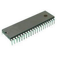
MC9S08AC16CBE
Description
IC MCU 8BIT 16K FLASH 42SDIP
Manufacturer
Freescale Semiconductor
Series
HCS08r
Specifications of MC9S08AC16CBE
Core Processor
HCS08
Core Size
8-Bit
Speed
40MHz
Connectivity
I²C, SCI, SPI
Peripherals
LVD, POR, PWM, WDT
Number Of I /o
32
Program Memory Size
16KB (16K x 8)
Program Memory Type
FLASH
Ram Size
1K x 8
Voltage - Supply (vcc/vdd)
2.7 V ~ 5.5 V
Data Converters
A/D 8x10b
Oscillator Type
Internal
Operating Temperature
-40°C ~ 85°C
Package / Case
42-DIP (0.600", 15.24mm)
Processor Series
S08AC
Core
HCS08
Data Bus Width
8 bit
Data Ram Size
1 KB
Interface Type
I2C, SCI, SPI
Maximum Clock Frequency
40 MHz
Number Of Programmable I/os
32
Operating Supply Voltage
2.7 V to 5.5 V
Maximum Operating Temperature
+ 85 C
Mounting Style
Through Hole
3rd Party Development Tools
EWS08
Development Tools By Supplier
DEMO9S08AC60E, DEMOACEX, DEMOACKIT, DCF51AC256, DC9S08AC128, DC9S08AC16, DC9S08AC60, DEMO51AC256KIT
Minimum Operating Temperature
- 40 C
Package
42SPDIP
Family Name
HCS08
Maximum Speed
40 MHz
On-chip Adc
8-chx10-bit
Number Of Timers
8
Lead Free Status / RoHS Status
Lead free / RoHS Compliant
Eeprom Size
-
Lead Free Status / Rohs Status
Details


11.2.5
This register has one read-only status flag.
Freescale Semiconductor
RXEDGIF
Reset
LBKDIF
RXINV
RWUID
BRK13
Field
Field
FE
PF
1
0
7
6
4
3
2
W
R
1
LBKDIF
SCI Status Register 2 (SCIxS2)
Framing Error Flag — FE is set at the same time as RDRF when the receiver detects a logic 0 where the stop
bit was expected. This suggests the receiver was not properly aligned to a character frame. To clear FE, read
SCIxS1 with FE = 1 and then read the SCI data register (SCIxD).
0 No framing error detected. This does not guarantee the framing is correct.
1 Framing error.
Parity Error Flag — PF is set at the same time as RDRF when parity is enabled (PE = 1) and the parity bit in
the received character does not agree with the expected parity value. To clear PF, read SCIxS1 and then read
the SCI data register (SCIxD).
0 No parity error.
1 Parity error.
LIN Break Detect Interrupt Flag — LBKDIF is set when the LIN break detect circuitry is enabled and a LIN break
character is detected. LBKDIF is cleared by writing a “1” to it.
0 No LIN break character has been detected.
1 LIN break character has been detected.
RxD Pin Active Edge Interrupt Flag — RXEDGIF is set when an active edge (falling if RXINV = 0, rising if
RXINV=1) on the RxD pin occurs. RXEDGIF is cleared by writing a “1” to it.
0 No active edge on the receive pin has occurred.
1 An active edge on the receive pin has occurred.
Receive Data Inversion — Setting this bit reverses the polarity of the received data input.
0 Receive data not inverted
1 Receive data inverted
Receive Wake Up Idle Detect— RWUID controls whether the idle character that wakes up the receiver sets the
IDLE bit.
0 During receive standby state (RWU = 1), the IDLE bit does not get set upon detection of an idle character.
1 During receive standby state (RWU = 1), the IDLE bit gets set upon detection of an idle character.
Break Character Generation Length — BRK13 is used to select a longer transmitted break character length.
Detection of a framing error is not affected by the state of this bit.
0 Break character is transmitted with length of 10 bit times (11 if M = 1)
1 Break character is transmitted with length of 13 bit times (14 if M = 1)
0
7
= Unimplemented or Reserved
RXEDGIF
0
6
Table 11-5. SCIxS1 Field Descriptions (continued)
Figure 11-9. SCI Status Register 2 (SCIxS2)
Table 11-6. SCIxS2 Field Descriptions
MC9S08AC16 Series Data Sheet, Rev. 8
0
0
5
RXINV
0
4
Description
Description
RWUID
3
0
Serial Communications Interface (S08SCIV4)
BRK13
0
2
LBKDE
0
1
RAF
0
0
199
Related parts for MC9S08AC16CBE
Image
Part Number
Description
Manufacturer
Datasheet
Request
R

Part Number:
Description:
Manufacturer:
Freescale Semiconductor, Inc
Datasheet:
Part Number:
Description:
Manufacturer:
Freescale Semiconductor, Inc
Datasheet:
Part Number:
Description:
Manufacturer:
Freescale Semiconductor, Inc
Datasheet:
Part Number:
Description:
Manufacturer:
Freescale Semiconductor, Inc
Datasheet:
Part Number:
Description:
Manufacturer:
Freescale Semiconductor, Inc
Datasheet:
Part Number:
Description:
Manufacturer:
Freescale Semiconductor, Inc
Datasheet:
Part Number:
Description:
Manufacturer:
Freescale Semiconductor, Inc
Datasheet:
Part Number:
Description:
Manufacturer:
Freescale Semiconductor, Inc
Datasheet:
Part Number:
Description:
Manufacturer:
Freescale Semiconductor, Inc
Datasheet:
Part Number:
Description:
Manufacturer:
Freescale Semiconductor, Inc
Datasheet:
Part Number:
Description:
Manufacturer:
Freescale Semiconductor, Inc
Datasheet:
Part Number:
Description:
Manufacturer:
Freescale Semiconductor, Inc
Datasheet:
Part Number:
Description:
Manufacturer:
Freescale Semiconductor, Inc
Datasheet:
Part Number:
Description:
Manufacturer:
Freescale Semiconductor, Inc
Datasheet:
Part Number:
Description:
Manufacturer:
Freescale Semiconductor, Inc
Datasheet: