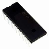
ST72F621J4B1 STMicroelectronics, ST72F621J4B1 Datasheet - Page 136

ST72F621J4B1
Manufacturer Part Number
ST72F621J4B1
Description
IC MCU 8BIT LS 16K 42-PDIP
Manufacturer
STMicroelectronics
Series
ST7r
Datasheet
1.ST72F622L2M1.pdf
(139 pages)
Specifications of ST72F621J4B1
Core Processor
ST7
Core Size
8-Bit
Speed
8MHz
Connectivity
SCI, SPI, USB
Peripherals
DMA, LVD, POR, PWM, WDT
Number Of I /o
31
Program Memory Size
16KB (16K x 8)
Program Memory Type
FLASH
Ram Size
768 x 8
Voltage - Supply (vcc/vdd)
4 V ~ 5.5 V
Data Converters
A/D 8x10b
Oscillator Type
Internal
Operating Temperature
0°C ~ 70°C
Package / Case
42-DIP (0.600", 15.24mm)
Processor Series
ST72F6x
Core
ST7
Data Bus Width
8 bit
Data Ram Size
768 B
Interface Type
SCI, SPI, USB
Maximum Clock Frequency
12 MHz
Number Of Programmable I/os
31
Number Of Timers
2
Operating Supply Voltage
4 V to 5.5 V
Maximum Operating Temperature
+ 70 C
Mounting Style
Through Hole
Minimum Operating Temperature
0 C
On-chip Adc
10 bit
For Use With
497-5046 - KIT TOOL FOR ST7/UPSD/STR7 MCU
Lead Free Status / RoHS Status
Contains lead / RoHS non-compliant
Eeprom Size
-
Lead Free Status / Rohs Status
In Transition
Other names
497-2110-5
Available stocks
Company
Part Number
Manufacturer
Quantity
Price
Company:
Part Number:
ST72F621J4B1
Manufacturer:
ST
Quantity:
329
15.3 SCI WRONG BREAK DURATION
Description
A single break character is sent by setting and re-
setting the SBK bit in the SCICR2 register. In
some cases, the break character may have a long-
er duration than expected:
– 20 bits instead of 10 bits if M=0
– 22 bits instead of 11 bits if M=1.
In the same way, as long as the SBK bit is set,
break characters are sent to the TDO pin. This
may lead to generate one break more than expect-
ed.
This affects all silicon revisions.
Occurrence
The occurrence of the problem is random and pro-
portional to the baudrate. With a transmit frequen-
cy of 19200 baud (f
BRR=0xC9), the wrong break duration occurrence
is around 1%.
Workaround
If this wrong duration is not compliant with the
communication protocol in the application, soft-
ware can request that an Idle line be generated
before the break character. In this case, the break
duration is always correct assuming the applica-
tion is not doing anything between the idle and the
break. This can be ensured by temporarily disa-
bling interrupts.
The exact sequence is:
– Disable interrupts
– Reset and Set TE (IDLE request)
– Set and Reset SBK (Break Request)
– Re-enable interrupts
136/139
CPU
=8MHz and SCI-
Doc ID 6996 Rev 5
15.4 UNEXPECTED RESET FETCH
If an interrupt request occurs while a "POP CC" in-
struction is executed, the interrupt controller does
not recognise the source of the interrupt and, by
default, passes the RESET vector address to the
CPU.
This affects all silicon revisions.
Workaround
To solve this issue, a "POP CC" instruction must
always be preceded by a "SIM" instruction.
15.5 HALT MODE POWER CONSUMPTION
WITH ADC ON
If the A/D converter is being used when Halt mode
is entered, the power consumption in Halt Mode
may exceed the maximum specified in the
datasheet.
This affects all silicon revisions.
Workaround
Switch off the ADC by software (ADON=0) before
executing a HALT instruction.


