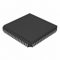
PIC18C858-I/L Microchip Technology, PIC18C858-I/L Datasheet - Page 24

PIC18C858-I/L
Manufacturer Part Number
PIC18C858-I/L
Description
IC PIC MCU OTP 16KX16 84PLCC
Manufacturer
Microchip Technology
Series
PIC® 18Cr
Datasheets
1.PIC16F616T-ISL.pdf
(8 pages)
2.PIC16C770-ISO.pdf
(8 pages)
3.PIC18C658-IPT.pdf
(366 pages)
4.PIC18C658-IPT.pdf
(16 pages)
5.PIC18C658-IPT.pdf
(16 pages)
6.PIC18C658-IPT.pdf
(16 pages)
Specifications of PIC18C858-I/L
Core Size
8-Bit
Program Memory Size
32KB (16K x 16)
Peripherals
Brown-out Detect/Reset, LVD, POR, PWM, WDT
Core Processor
PIC
Speed
40MHz
Connectivity
CAN, I²C, SPI, UART/USART
Number Of I /o
68
Program Memory Type
OTP
Ram Size
1.5K x 8
Voltage - Supply (vcc/vdd)
4.2 V ~ 5.5 V
Data Converters
A/D 16x10b
Oscillator Type
External
Operating Temperature
-40°C ~ 85°C
Package / Case
84-PLCC
Controller Family/series
PIC18
No. Of I/o's
68
Ram Memory Size
1.5KB
Cpu Speed
40MHz
No. Of Timers
4
Processor Series
PIC18C
Core
PIC
Data Bus Width
8 bit
Data Ram Size
1536 B
Interface Type
3-Wire, I2C, SPI, USART, CAN
Maximum Clock Frequency
40 MHz
Number Of Programmable I/os
68
Number Of Timers
4 bit
Operating Supply Voltage
2.5 V to 5.5 V
Maximum Operating Temperature
+ 85 C
Mounting Style
SMD/SMT
3rd Party Development Tools
52715-96, 52716-328, 52717-734, 52712-325, EWPIC18
Development Tools By Supplier
ICE2000, DM163007, DV164136
Minimum Operating Temperature
- 40 C
On-chip Adc
6
Lead Free Status / RoHS Status
Lead free / RoHS Compliant
For Use With
AC164310 - MODULE SKT FOR PM3 84PLCCDVA18XL840 - ADAPTER DEVICE ICE 84PLCCAC174012 - MODULE SKT PROMATEII 84PLCC
Eeprom Size
-
Lead Free Status / Rohs Status
Details
Other names
PIC18C858I/L
Available stocks
Company
Part Number
Manufacturer
Quantity
Price
Company:
Part Number:
PIC18C858-I/L
Manufacturer:
Microchip
Quantity:
3 097
Company:
Part Number:
PIC18C858-I/L
Manufacturer:
Microchip Technology
Quantity:
10 000
- PIC16F616T-ISL PDF datasheet
- PIC16C770-ISO PDF datasheet #2
- PIC18C658-IPT PDF datasheet #3
- PIC18C658-IPT PDF datasheet #4
- PIC18C658-IPT PDF datasheet #5
- PIC18C658-IPT PDF datasheet #6
- Current page: 24 of 366
- Download datasheet (7Mb)
PIC18CXX8
2.5
A Phase Locked Loop circuit is provided as a pro-
grammable option for users that want to multiply the
frequency of the incoming crystal oscillator signal by 4.
For an input clock frequency of 10 MHz, the internal
clock frequency will be multiplied to 40 MHz. This is
useful for customers who are concerned with EMI due
to high frequency crystals.
FIGURE 2-5:
DS30475A-page 24
HS4 (PLL)
OSC2
OSC1
PLL BLOCK DIAGRAM
Crystal
Osc
F
IN
Comparator
F
OUT
Phase
Advanced Information
FOSC2:FOSC0 = ‘110’
Loop
Filter
The PLL can only be enabled when the oscillator con-
figuration bits are programmed for HS mode. If they
are programmed for any other mode, the PLL is not
enabled and the system clock will come directly from
OSC1.
The PLL is one of the modes of the FOSC2:FOSC0
configuration bits. The oscillator mode is specified dur-
ing device programming.
A PLL lock timer is used to ensure that the PLL has
locked before device execution starts. The PLL lock
timer has a time-out referred to as T
Divide by 4
VCO
2000 Microchip Technology Inc.
PLL
.
SYSCLK
Related parts for PIC18C858-I/L
Image
Part Number
Description
Manufacturer
Datasheet
Request
R

Part Number:
Description:
IC, 8BIT MCU, PIC18F, 40MHZ, LCC-44
Manufacturer:
Microchip Technology
Datasheet:

Part Number:
Description:
IC, 8BIT MCU, PIC18LF, 40MHZ, PLCC-64
Manufacturer:
Microchip Technology
Datasheet:

Part Number:
Description:
IC, 8BIT MCU, PIC18F, 64MHZ, TQFP-80
Manufacturer:
Microchip Technology
Datasheet:

Part Number:
Description:
MCU, MPU & DSP Development Tools CAN/LIN PICtail Plus Daughter Board
Manufacturer:
Microchip Technology
Datasheet:

Part Number:
Description:
IC, 8BIT MCU, PIC18F, 64MHZ, DIP-40
Manufacturer:
Microchip Technology
Datasheet:

Part Number:
Description:
IC, 8BIT MCU, PIC18LF, 40MHZ, PLCC-64
Manufacturer:
Microchip Technology
Datasheet:

Part Number:
Description:
IC, 8BIT MCU, PIC18F, 64MHZ, TQFP-64
Manufacturer:
Microchip Technology

Part Number:
Description:
IC, 8BIT MCU, PIC18F, 64MHZ, TQFP-80
Manufacturer:
Microchip Technology

Part Number:
Description:
8KB, Flash, 768bytes-RAM, 36I/O, 8-bit Family,nanowatt XLP 40 UQFN 5x5x0.5mm TUB
Manufacturer:
Microchip Technology
Datasheet:

Part Number:
Description:
8KB, Flash, 768bytes-RAM, 36I/O, 8-bit Family,nanowatt XLP 40 UQFN 5x5x0.5mm TUB
Manufacturer:
Microchip Technology

Part Number:
Description:
16KB, Flash, 768bytes-RAM, 36I/O, 8-bit Family,nanowatt XLP 40 UQFN 5x5x0.5mm TU
Manufacturer:
Microchip Technology
Datasheet:

Part Number:
Description:
16KB, Flash, 768bytes-RAM, 36I/O, 8-bit Family,nanowatt XLP 40 UQFN 5x5x0.5mm TU
Manufacturer:
Microchip Technology

Part Number:
Description:
32KB, Flash, 1536bytes-RAM, 36I/O, 8-bit Family,nanowatt XLP 40 UQFN 5x5x0.5mm T
Manufacturer:
Microchip Technology
Datasheet:

Part Number:
Description:
32KB, Flash, 1536bytes-RAM, 36I/O, 8-bit Family,nanowatt XLP 40 UQFN 5x5x0.5mm T
Manufacturer:
Microchip Technology

Part Number:
Description:
64KB, Flash, 3968bytes-RAM, 36I/O, 8-bit Family,nanowatt XLP 40 UQFN 5x5x0.5mm T
Manufacturer:
Microchip Technology
Datasheet:


