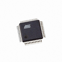
AT91SAM7S32B-AU Atmel, AT91SAM7S32B-AU Datasheet - Page 379

AT91SAM7S32B-AU
Manufacturer Part Number
AT91SAM7S32B-AU
Description
IC MCU ARM7 32KB FLASH 48LQFP
Manufacturer
Atmel
Series
AT91SAMr
Datasheet
1.AT91SAM7S16-MU.pdf
(779 pages)
Specifications of AT91SAM7S32B-AU
Core Processor
ARM7
Core Size
16/32-Bit
Speed
55MHz
Connectivity
I²C, SPI, SSC, UART/USART
Peripherals
Brown-out Detect/Reset, DMA, POR, PWM, WDT
Number Of I /o
21
Program Memory Size
32KB (32K x 8)
Program Memory Type
FLASH
Ram Size
8K x 8
Voltage - Supply (vcc/vdd)
1.65 V ~ 1.95 V
Data Converters
A/D 8x10b
Oscillator Type
Internal
Operating Temperature
-40°C ~ 85°C
Package / Case
48-LQFP
Cpu Family
91S
Device Core
ARM7TDMI
Device Core Size
32b
Frequency (max)
55MHz
Interface Type
SPI/TWI/USART
Total Internal Ram Size
8KB
# I/os (max)
21
Number Of Timers - General Purpose
3
Operating Supply Voltage (typ)
1.8/3.3V
Operating Supply Voltage (max)
1.95/3.6V
Operating Supply Voltage (min)
1.65/3V
On-chip Adc
8-chx10-bit
Instruction Set Architecture
RISC
Operating Temp Range
-40C to 85C
Operating Temperature Classification
Industrial
Mounting
Surface Mount
Pin Count
48
Package Type
LQFP
Package
48LQFP
Family Name
AT91
Maximum Speed
55 MHz
Operating Supply Voltage
1.8|3.3 V
Data Bus Width
32 Bit
Number Of Programmable I/os
21
Number Of Timers
3
For Use With
AT91SAM-ICE - EMULATOR FOR AT91 ARM7/ARM9AT91SAM7S-EK - KIT EVAL FOR ARM AT91SAM7S
Lead Free Status / RoHS Status
Lead free / RoHS Compliant
Eeprom Size
-
Lead Free Status / Rohs Status
Compliant
Available stocks
Company
Part Number
Manufacturer
Quantity
Price
Part Number:
AT91SAM7S32B-AU
Manufacturer:
MICROCHIP/微芯
Quantity:
20 000
- Current page: 379 of 779
- Download datasheet (11Mb)
31.6.5.1
31.6.5.2
6175K–ATARM–30-Aug-10
IrDA Modulation
IrDA Baud Rate
For baud rates up to and including 115.2 Kbits/sec, the RZI modulation scheme is used. “0” is
represented by a light pulse of 3/16th of a bit time. Some examples of signal pulse duration are
shown in
Table 31-9.
Figure 31-26
Figure 31-26. IrDA Modulation
Table 31-10
the requirement on the maximum acceptable error of ±1.87% must be met.
Table 31-10. IrDA Baud Rate Error
Baud Rate
2.4 Kb/s
9.6 Kb/s
19.2 Kb/s
38.4 Kb/s
57.6 Kb/s
115.2 Kb/s
Peripheral Clock
3 686 400
20 000 000
32 768 000
40 000 000
3 686 400
20 000 000
32 768 000
• Configure the TXD pin as PIO and set it as an output at 0 (to avoid LED emission). Disable
• Receive data
the internal pull-up (better for power consumption).
Table
gives some examples of CD values, baud rate error and pulse duration. Note that
shows an example of character transmission.
Transmitter
IrDA Pulse Duration
31-9.
Output
TXD
Baud Rate
115 200
115 200
115 200
115 200
57 600
57 600
57 600
Bit Period
Start
Bit
0
AT91SAM7S Series Preliminary
1
0
Pulse Duration (3/16)
78.13 µs
19.53 µs
9.77 µs
4.88 µs
3.26 µs
1.63 µs
1
CD
11
18
22
22
36
2
4
Data Bits
0
0
Baud Rate Error
1
0.00%
1.38%
1.25%
1.38%
0.00%
1.38%
1.25%
1
16
3
0
Bit Period
Stop
Bit
1
Pulse Time
1.63
1.63
1.63
1.63
3.26
3.26
3.26
379
Related parts for AT91SAM7S32B-AU
Image
Part Number
Description
Manufacturer
Datasheet
Request
R

Part Number:
Description:
KIT EVAL FOR ARM AT91SAM7S
Manufacturer:
Atmel
Datasheet:

Part Number:
Description:
MCU, MPU & DSP Development Tools KICKSTART KIT ATMEL AT91SAM7S
Manufacturer:
IAR Systems

Part Number:
Description:
DEV KIT FOR AVR/AVR32
Manufacturer:
Atmel
Datasheet:

Part Number:
Description:
INTERVAL AND WIPE/WASH WIPER CONTROL IC WITH DELAY
Manufacturer:
ATMEL Corporation
Datasheet:

Part Number:
Description:
Low-Voltage Voice-Switched IC for Hands-Free Operation
Manufacturer:
ATMEL Corporation
Datasheet:

Part Number:
Description:
MONOLITHIC INTEGRATED FEATUREPHONE CIRCUIT
Manufacturer:
ATMEL Corporation
Datasheet:

Part Number:
Description:
AM-FM Receiver IC U4255BM-M
Manufacturer:
ATMEL Corporation
Datasheet:

Part Number:
Description:
Monolithic Integrated Feature Phone Circuit
Manufacturer:
ATMEL Corporation
Datasheet:

Part Number:
Description:
Multistandard Video-IF and Quasi Parallel Sound Processing
Manufacturer:
ATMEL Corporation
Datasheet:

Part Number:
Description:
High-performance EE PLD
Manufacturer:
ATMEL Corporation
Datasheet:

Part Number:
Description:
8-bit Flash Microcontroller
Manufacturer:
ATMEL Corporation
Datasheet:

Part Number:
Description:
2-Wire Serial EEPROM
Manufacturer:
ATMEL Corporation
Datasheet:


