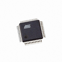
AT91SAM7S32B-AU Atmel, AT91SAM7S32B-AU Datasheet - Page 168

AT91SAM7S32B-AU
Manufacturer Part Number
AT91SAM7S32B-AU
Description
IC MCU ARM7 32KB FLASH 48LQFP
Manufacturer
Atmel
Series
AT91SAMr
Datasheet
1.AT91SAM7S16-MU.pdf
(779 pages)
Specifications of AT91SAM7S32B-AU
Core Processor
ARM7
Core Size
16/32-Bit
Speed
55MHz
Connectivity
I²C, SPI, SSC, UART/USART
Peripherals
Brown-out Detect/Reset, DMA, POR, PWM, WDT
Number Of I /o
21
Program Memory Size
32KB (32K x 8)
Program Memory Type
FLASH
Ram Size
8K x 8
Voltage - Supply (vcc/vdd)
1.65 V ~ 1.95 V
Data Converters
A/D 8x10b
Oscillator Type
Internal
Operating Temperature
-40°C ~ 85°C
Package / Case
48-LQFP
Cpu Family
91S
Device Core
ARM7TDMI
Device Core Size
32b
Frequency (max)
55MHz
Interface Type
SPI/TWI/USART
Total Internal Ram Size
8KB
# I/os (max)
21
Number Of Timers - General Purpose
3
Operating Supply Voltage (typ)
1.8/3.3V
Operating Supply Voltage (max)
1.95/3.6V
Operating Supply Voltage (min)
1.65/3V
On-chip Adc
8-chx10-bit
Instruction Set Architecture
RISC
Operating Temp Range
-40C to 85C
Operating Temperature Classification
Industrial
Mounting
Surface Mount
Pin Count
48
Package Type
LQFP
Package
48LQFP
Family Name
AT91
Maximum Speed
55 MHz
Operating Supply Voltage
1.8|3.3 V
Data Bus Width
32 Bit
Number Of Programmable I/os
21
Number Of Timers
3
For Use With
AT91SAM-ICE - EMULATOR FOR AT91 ARM7/ARM9AT91SAM7S-EK - KIT EVAL FOR ARM AT91SAM7S
Lead Free Status / RoHS Status
Lead free / RoHS Compliant
Eeprom Size
-
Lead Free Status / Rohs Status
Compliant
Available stocks
Company
Part Number
Manufacturer
Quantity
Price
Part Number:
AT91SAM7S32B-AU
Manufacturer:
MICROCHIP/微芯
Quantity:
20 000
- Current page: 168 of 779
- Download datasheet (11Mb)
23.7.3
23.7.3.1
23.7.3.2
23.7.3.3
168
AT91SAM7S Series Preliminary
Normal Interrupt
Priority Controller
Interrupt Nesting
Interrupt Vectoring
An 8-level priority controller drives the nIRQ line of the processor, depending on the interrupt
conditions occurring on the interrupt sources 1 to 31 (except for those programmed in Fast
Forcing).
Each interrupt source has a programmable priority level of 7 to 0, which is user-definable by writ-
ing the PRIOR field of the corresponding AIC_SMR (Source Mode Register). Level 7 is the
highest priority and level 0 the lowest.
As soon as an interrupt condition occurs, as defined by the SRCTYPE field of the AIC_SMR
(Source Mode Register), the nIRQ line is asserted. As a new interrupt condition might have hap-
pened on other interrupt sources since the nIRQ has been asserted, the priority controller
determines the current interrupt at the time the AIC_IVR (Interrupt Vector Register) is read. The
read of AIC_IVR is the entry point of the interrupt handling which allows the AIC to consider
that the interrupt has been taken into account by the software.
The current priority level is defined as the priority level of the current interrupt.
If several interrupt sources of equal priority are pending and enabled when the AIC_IVR is read,
the interrupt with the lowest interrupt source number is serviced first.
The nIRQ line can be asserted only if an interrupt condition occurs on an interrupt source with a
higher priority. If an interrupt condition happens (or is pending) during the interrupt treatment in
progress, it is delayed until the software indicates to the AIC the end of the current service by
writing the AIC_EOICR (End of Interrupt Command Register). The write of AIC_EOICR is the
exit point of the interrupt handling.
The priority controller utilizes interrupt nesting in order for the high priority interrupt to be handled
during the service of lower priority interrupts. This requires the interrupt service routines of the
lower interrupts to re-enable the interrupt at the processor level.
When an interrupt of a higher priority happens during an already occurring interrupt service rou-
tine, the nIRQ line is re-asserted. If the interrupt is enabled at the core level, the current
execution is interrupted and the new interrupt service routine should read the AIC_IVR. At this
time, the current interrupt number and its priority level are pushed into an embedded hardware
stack, so that they are saved and restored when the higher priority interrupt servicing is finished
and the AIC_EOICR is written.
The AIC is equipped with an 8-level wide hardware stack in order to support up to eight interrupt
nestings pursuant to having eight priority levels.
The interrupt handler addresses corresponding to each interrupt source can be stored in the reg-
isters AIC_SVR1 to AIC_SVR31 (Source Vector Register 1 to 31). When the processor reads
AIC_IVR (Interrupt Vector Register), the value written into AIC_SVR corresponding to the cur-
rent interrupt is returned.
This feature offers a way to branch in one single instruction to the handler corresponding to the
current interrupt, as AIC_IVR is mapped at the absolute address 0xFFFF F100 and thus acces-
sible from the ARM interrupt vector at address 0x0000 0018 through the following instruction:
LDR
PC,[PC,# -&F20]
6175K–ATARM–30-Aug-10
Related parts for AT91SAM7S32B-AU
Image
Part Number
Description
Manufacturer
Datasheet
Request
R

Part Number:
Description:
KIT EVAL FOR ARM AT91SAM7S
Manufacturer:
Atmel
Datasheet:

Part Number:
Description:
MCU, MPU & DSP Development Tools KICKSTART KIT ATMEL AT91SAM7S
Manufacturer:
IAR Systems

Part Number:
Description:
DEV KIT FOR AVR/AVR32
Manufacturer:
Atmel
Datasheet:

Part Number:
Description:
INTERVAL AND WIPE/WASH WIPER CONTROL IC WITH DELAY
Manufacturer:
ATMEL Corporation
Datasheet:

Part Number:
Description:
Low-Voltage Voice-Switched IC for Hands-Free Operation
Manufacturer:
ATMEL Corporation
Datasheet:

Part Number:
Description:
MONOLITHIC INTEGRATED FEATUREPHONE CIRCUIT
Manufacturer:
ATMEL Corporation
Datasheet:

Part Number:
Description:
AM-FM Receiver IC U4255BM-M
Manufacturer:
ATMEL Corporation
Datasheet:

Part Number:
Description:
Monolithic Integrated Feature Phone Circuit
Manufacturer:
ATMEL Corporation
Datasheet:

Part Number:
Description:
Multistandard Video-IF and Quasi Parallel Sound Processing
Manufacturer:
ATMEL Corporation
Datasheet:

Part Number:
Description:
High-performance EE PLD
Manufacturer:
ATMEL Corporation
Datasheet:

Part Number:
Description:
8-bit Flash Microcontroller
Manufacturer:
ATMEL Corporation
Datasheet:

Part Number:
Description:
2-Wire Serial EEPROM
Manufacturer:
ATMEL Corporation
Datasheet:


