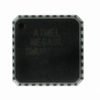
ATMEGA8L-8MU Atmel, ATMEGA8L-8MU Datasheet - Page 24

ATMEGA8L-8MU
Manufacturer Part Number
ATMEGA8L-8MU
Description
IC AVR MCU 8K 8MHZ 3V 32-QFN
Manufacturer
Atmel
Series
AVR® ATmegar
Specifications of ATMEGA8L-8MU
Core Processor
AVR
Core Size
8-Bit
Speed
8MHz
Connectivity
I²C, SPI, UART/USART
Peripherals
Brown-out Detect/Reset, POR, PWM, WDT
Number Of I /o
23
Program Memory Size
8KB (4K x 16)
Program Memory Type
FLASH
Eeprom Size
512 x 8
Ram Size
1K x 8
Voltage - Supply (vcc/vdd)
2.7 V ~ 5.5 V
Data Converters
A/D 8x10b
Oscillator Type
Internal
Operating Temperature
-40°C ~ 85°C
Package / Case
32-VQFN Exposed Pad, 32-HVQFN, 32-SQFN, 32-DHVQFN
Package
32MLF EP
Device Core
AVR
Family Name
ATmega
Maximum Speed
8 MHz
Operating Supply Voltage
3.3|5 V
Data Bus Width
8 Bit
Number Of Programmable I/os
23
Interface Type
SPI/TWI/USART
On-chip Adc
8-chx10-bit
Number Of Timers
3
Controller Family/series
AVR MEGA
No. Of I/o's
23
Eeprom Memory Size
512Byte
Ram Memory Size
1KB
Cpu Speed
8MHz
Rohs Compliant
Yes
For Use With
ATSTK600-TQFP32 - STK600 SOCKET/ADAPTER 32-TQFPATSTK600-DIP40 - STK600 SOCKET/ADAPTER 40-PDIP770-1007 - ISP 4PORT ATMEL AVR MCU SPI/JTAGATAVRISP2 - PROGRAMMER AVR IN SYSTEMATSTK500 - PROGRAMMER AVR STARTER KIT
Lead Free Status / RoHS Status
Lead free / RoHS Compliant
Available stocks
Company
Part Number
Manufacturer
Quantity
Price
Part Number:
ATMEGA8L-8MU
Manufacturer:
AT
Quantity:
20 000
Changes from Rev.
2486B-12/01 to
Rev. 2486C-03/02
1. Updated TWI Chapter.
2. Updated Description of OSCCAL Calibration Byte.
3. Added Some Preliminary Test Limits and Characterization Data.
4. Updated Programming Figures.
5. Added a Description on how to Enter Parallel Programming Mode if RESET Pin is Dis-
More details regarding use of the TWI Power-down operation and using the TWI as Master
with low TWBRR values are added into the datasheet.
Added the note at the end of the
Added the description at the end of
In the datasheet, it was not explained how to take advantage of the calibration bytes for 2, 4,
and 8 MHz Oscillator selections. This is now added in the following sections:
Improved description of
bration Byte” on page
Removed some of the TBD’s in the following tables and pages:
Table 3 on page
-40°C to +85°C, VCC = 2.7V to 5.5V (unless otherwise noted)” on page
page
Figure 104 on page 219
must be connected during Programming mode.
abled or if External Oscillators are Selected.
Added a note in section
237, and
Table 102 on page
26,
Table 15 on page
218.
“Enter Programming Mode” on page
“Oscillator Calibration Register – OSCCAL” on page 31
and
Figure 112 on page 230
“Bit Rate Generator Unit” on page
239.
“Address Match Unit” on page
38,
Table 16 on page
are updated to also reflect that AV
42,
221.
Table 17 on page
164.
164.
235,
Table 99 on
and
44,
“Cali-
“T
A
CC
=


