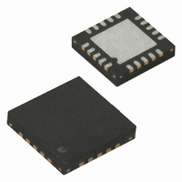
ATTINY2313-20MU Atmel, ATTINY2313-20MU Datasheet - Page 34

ATTINY2313-20MU
Manufacturer Part Number
ATTINY2313-20MU
Description
IC MCU AVR 2K FLASH 20MLF
Manufacturer
Atmel
Series
AVR® ATtinyr
Specifications of ATTINY2313-20MU
Core Processor
AVR
Core Size
8-Bit
Speed
20MHz
Connectivity
SPI, UART/USART
Peripherals
Brown-out Detect/Reset, POR, PWM, WDT
Number Of I /o
18
Program Memory Size
2KB (1K x 16)
Program Memory Type
FLASH
Eeprom Size
128 x 8
Ram Size
128 x 8
Voltage - Supply (vcc/vdd)
2.7 V ~ 5.5 V
Oscillator Type
Internal
Operating Temperature
-40°C ~ 85°C
Package / Case
20-MLF®, QFN
Processor Series
ATTINY2x
Core
AVR8
Data Bus Width
8 bit
Data Ram Size
128 B
Interface Type
SPI/UART/USI
Maximum Clock Frequency
20 MHz
Number Of Programmable I/os
18
Number Of Timers
2
Operating Supply Voltage
2.7 V to 5.5 V
Maximum Operating Temperature
+ 85 C
Mounting Style
SMD/SMT
3rd Party Development Tools
EWAVR, EWAVR-BL
Development Tools By Supplier
ATAVRDRAGON, ATSTK500, ATSTK600, ATAVRISP2, ATAVRONEKIT
Minimum Operating Temperature
- 40 C
Package
20MLF EP
Device Core
AVR
Family Name
ATtiny
Maximum Speed
20 MHz
For Use With
ATSTK600-DIP40 - STK600 SOCKET/ADAPTER 40-PDIP770-1007 - ISP 4PORT ATMEL AVR MCU SPI/JTAGATAVRDRAGON - KIT DRAGON 32KB FLASH MEM AVRATAVRISP2 - PROGRAMMER AVR IN SYSTEMATJTAGICE2 - AVR ON-CHIP D-BUG SYSTEM
Lead Free Status / RoHS Status
Lead free / RoHS Compliant
Data Converters
-
Lead Free Status / Rohs Status
Lead free / RoHS Compliant
Other names
Q2312268A
Available stocks
Company
Part Number
Manufacturer
Quantity
Price
Part Number:
ATTINY2313-20MU
Manufacturer:
原装ATMEL
Quantity:
20 000
- Current page: 34 of 226
- Download datasheet (4Mb)
Power-on Reset
34
ATtiny2313
Table 15. Reset Characteristics
Notes:
A Power-on Reset (POR) pulse is generated by an On-chip detection circuit. The detection level
is defined in
POR circuit can be used to trigger the start-up Reset, as well as to detect a failure in supply
voltage.
A Power-on Reset (POR) circuit ensures that the device is reset from Power-on. Reaching the
Power-on Reset threshold voltage invokes the delay counter, which determines how long the
device is kept in RESET after V
when V
Figure 15. MCU Start-up, RESET Tied to V
Symbol
V
V
t
RST
POT
RST
INTERNAL
TIME-OUT
CC
RESET
1. Values are guidelines only. Actual values are TBD.
2. The Power-on Reset will not work unless the supply voltage has been below V
RESET
V
decreases below the detection level.
CC
Power-on Reset
Threshold Voltage
(rising)
Power-on Reset
Threshold Voltage
(falling)
Voltage
Minimum pulse width
on RESET Pin
RESET Pin Threshold
Table
Parameter
(2)
15. The POR is activated whenever V
V
V
POT
RST
CC
t
TOUT
rise. The RESET signal is activated again, without any delay,
T
T
A
V
V
A
= -40 - to +85°C
CC
CC
= -40 to +85°C
Condition
= 1.8 - 5.5V
= 1.8 - 5.5V
CC
0.2 V
Min
CC
is below the detection level. The
(1)
CC
Typ
1.2
1.1
(1)
0.9 V
Max
2.5
POT
(1)
CC
2543L–AVR–08/10
(falling)
Units
µs
V
V
V
Related parts for ATTINY2313-20MU
Image
Part Number
Description
Manufacturer
Datasheet
Request
R

Part Number:
Description:
IC, MCU, 8BIT, 2K FLASH, 20SOIC
Manufacturer:
Atmel
Datasheet:

Part Number:
Description:
IC, MCU, 8BIT, 2K FLASH, 20PDIP
Manufacturer:
Atmel
Datasheet:

Part Number:
Description:
IC, MCU, 8BIT, 8K FLASH, 20PDIP
Manufacturer:
Atmel
Datasheet:

Part Number:
Description:
IC, MCU, 8BIT, 8K FLASH, 20SOIC
Manufacturer:
Atmel
Datasheet:

Part Number:
Description:
DEV KIT FOR AVR/AVR32
Manufacturer:
Atmel
Datasheet:

Part Number:
Description:
INTERVAL AND WIPE/WASH WIPER CONTROL IC WITH DELAY
Manufacturer:
ATMEL Corporation
Datasheet:

Part Number:
Description:
Low-Voltage Voice-Switched IC for Hands-Free Operation
Manufacturer:
ATMEL Corporation
Datasheet:

Part Number:
Description:
MONOLITHIC INTEGRATED FEATUREPHONE CIRCUIT
Manufacturer:
ATMEL Corporation
Datasheet:

Part Number:
Description:
AM-FM Receiver IC U4255BM-M
Manufacturer:
ATMEL Corporation
Datasheet:

Part Number:
Description:
Monolithic Integrated Feature Phone Circuit
Manufacturer:
ATMEL Corporation
Datasheet:

Part Number:
Description:
Multistandard Video-IF and Quasi Parallel Sound Processing
Manufacturer:
ATMEL Corporation
Datasheet:

Part Number:
Description:
High-performance EE PLD
Manufacturer:
ATMEL Corporation
Datasheet:


