JBXER0G07FSSDPR Souriau Connection Technology, JBXER0G07FSSDPR Datasheet - Page 11
JBXER0G07FSSDPR
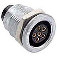
Manufacturer Part Number
JBXER0G07FSSDPR
Description
CONN RCPT 7POS FRONT PNL MNT SLD
Manufacturer
Souriau Connection Technology
Series
JBXr
Specifications of JBXER0G07FSSDPR
Connector Type
Receptacle, Female Sockets
Number Of Positions
7
Mounting Type
Panel Mount, Bulkhead - Rear Side Nut
Termination
Solder
Fastening Type
Push-Pull
Orientation
G
Shell Material, Finish
Brass, Chrome over Nickel
Features
Shielded
Connector Body Material
Brass
Gender
Receptacle
Contact Gender
Socket
Connector Mounting
Panel
Product Type
Connectors
Shell Style
Receptacle
Number Of Contacts
7
Lead Free Status / RoHS Status
Lead free / RoHS Compliant
Ingress Protection
-
Shell Size, Military
-
Lead Free Status / Rohs Status
Lead free / RoHS Compliant
Other names
JBXER0G07FSSDPR
SOU1625
SOU1625


Contact layouts
• Multi contact inserts
• Voltage Test Procedure
- The testing voltage corresponds to the maximum voltage the connector is able to withstand in normal climatic conditions.
- The working voltage corresponds to the maximum voltage the connector is able to withstand continuously during its life
• Maximum current rating
- This indicated maximum current rating corresponds to the maximum current that can be continuously applied to the connector
Remark : If the current is applied on only one contact of the layout, then an increased current value can be achieved over a long
duration.
* For receptacles with female contacts.
Note : Contacts are numbered counter clock wise in the plug and clock wise in the receptacle.
The value is about 75% of the electrical breakdown voltage. The testing voltage level can be reached several times in
connectors life, but never applied for a continuous duration.
time, in real environmental conditions, even with high temperature. The value is around 1/3 of the testing voltage.
mated pair, in normal climatic conditions.
Shell
size
3
viewed from
Inserts with fixed contacts (non removable contacts).
wiring side
insulator
Male
Contact
layout
side
07
30
10
14
18
22
solder
S
S
S
S
S
S
S
Contact types available
crimp
C
C
C
C
C
C
C
JBX Series
PCB tails PCB tails
straight
P*
P
P
P
P
90°
Q*
12
Contact
1.6
1.3
0.9
0.9
0.7
0.7
Ø
Solder
Max.
wire
18
26
20
24
24
26
AWG
Crimp
wire
Max.
14
26
18
20
20
22
current
rating
Max.
(A)*
3.5
5.5
15
12
9
7
(Vrms)*
voltage
Testing
2200
1400
1700
1400
1200
800
Working
1000/730
voltage
Vrms)*
400/260
660/460
830/560
660/460
560/400
(Vdc /
Related parts for JBXER0G07FSSDPR
Image
Part Number
Description
Manufacturer
Datasheet
Request
R

Part Number:
Description:
CONN SEALING FOR WALL RCPT #22
Manufacturer:
Souriau Connection Technology
Part Number:
Description:
CONN SEALING FOR WALL RCPT #14
Manufacturer:
Souriau Connection Technology
Datasheet:

Part Number:
Description:
CONN RCPT SEALING CAP SIZE 10
Manufacturer:
Souriau Connection Technology
Datasheet:

Part Number:
Description:
CONN RCPT SEALING CAP SIZE 14
Manufacturer:
Souriau Connection Technology
Datasheet:

Part Number:
Description:
CONN STRAIN RELIEF 12POS
Manufacturer:
Souriau Connection Technology
Datasheet:

Part Number:
Description:
D38999 Series 3
Manufacturer:
Souriau Connection Technology
Datasheet: