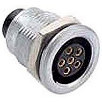
JBXER0G07FSSDPR Souriau Connection Technology, JBXER0G07FSSDPR Datasheet

JBXER0G07FSSDPR
Specifications of JBXER0G07FSSDPR
SOU1625
Related parts for JBXER0G07FSSDPR
JBXER0G07FSSDPR Summary of contents
Page 1
JBX RECEPTACLE ASSEMBLY INSTRUCTIONS 1. Select the proper JBX receptacle and contact size for the specific cable application by using the contact layout chart as depicted in the Push Pull catalog. 2. Strip the cable/wire to the required strip length. ...
Page 2
Wiring and assembly instructions Cable stripping for connectors with crimp contacts Shell size Ø contacts 0.7 0 0.9 0.7 1 0.9 1.3 0.7 0.9 2 1.3 1.6 2.0 0.7 0.9 3 1.3 1.6 2.0 Wiring and assembly instructions Cable stripping ...
Page 3
Depending on application and shell type, the nut and washer may be removed before attaching the wires to the contacts. 4. Attach crimped contacts to wires using crimped contacts, crimp the contacts onto the ends of the ...
Page 4
Crimping Tool Specifications MIL-C-22520 / 7.01 Specifications MIL-C-22520 / 1. using clipped solder contacts, prep each wire with flux and then tin dip each exposed wire end. Next pre-load a piece of heat shrink onto the wire (Individual ...
Page 5
Removal of contacts: a. Using the proper extraction tool (See FIGURE 6.A), insert the tool over the front of the contact and push contact out. Failure to use the proper extraction tool can result in damage to the contact. ...
Page 6
Potting of backend of receptacle with clipped contacts Clipped contacts are designed to float in the connector so that they self align when mated sometimes necessary to pot the backend of the connector so that the contacts ...


