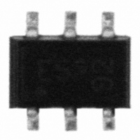
ESD5V0S5US E6327 Infineon Technologies, ESD5V0S5US E6327 Datasheet - Page 5

ESD5V0S5US E6327
Manufacturer Part Number
ESD5V0S5US E6327
Description
DIODES TVS UNIDIRECT SOT-363
Manufacturer
Infineon Technologies
Datasheet
1.ESD5V0S5US_E6327.pdf
(7 pages)
Specifications of ESD5V0S5US E6327
Package / Case
SC-70-6, SC-88, SOT-363
Voltage - Reverse Standoff (typ)
5V
Voltage - Breakdown
5.7V
Power (watts)
130W
Polarization
5 Channel Array - Unidirectional
Mounting Type
Surface Mount
Polarity
Unidirectional
Clamping Voltage
13 V
Operating Voltage
5.3 V
Breakdown Voltage
5.7 V
Peak Surge Current
10 A
Peak Pulse Power Dissipation
130 W
Maximum Operating Temperature
+ 125 C
Minimum Operating Temperature
- 55 C
Dimensions
1.25 mm W x 2 mm L
Lead Free Status / RoHS Status
Lead free / RoHS Compliant
Lead Free Status / RoHS Status
Lead free / RoHS Compliant, Lead free / RoHS Compliant
Other names
5V0S5USE6327XT
ESD5V0S5US E6327
ESD5V0S5USE6327INTR
ESD5V0S5USE6327T
SP000205611
ESD5V0S5US E6327
ESD5V0S5USE6327INTR
ESD5V0S5USE6327T
SP000205611
Application example ESD5V0S5US
5 channels, uni-directional
Application example ESD5V0S5US
4 channels, bi-directional
Application example ESD5V0S4US
4 channels, uni-directional
4 protected signal lines, level -5.3V ... +5.3V
5 protected signal lines, level 0 ... +5.3V
4 protected signal lines, level 0 … +5.3V
3
4
6
1
4
3
2
5
2
5
5
2
4
3
1
1
6
6
5
The protection diode should be placed
very close to the location where the
ESD or other transients can occur to
keep loops and inductances as small
as possible.
Pin 5 should be connected directly to a
ground plane on the board.
For bi-directional protection pin 2
(or any other pin except pin 5)
should be connected directly to a
ground plane on the board.
Pin 5 is not connected. Total
clamping voltage is the sum of
V
Pin 2 and pin 5 should be
connected directly to a ground
plane on the board.
CL
+ V
FC
(see table on page 2).
I/O
I/O
I/O
I/O
I/O
I/O
I/O
I/O
I/O
I/O
I/O
I/O
I/O
ESD sensitive
ESD sensitive
ESD sensitive
device
device
device
ESD5V0SxUS
2007-12-11


