1055449-1 Tyco Electronics, 1055449-1 Datasheet - Page 4
1055449-1
Manufacturer Part Number
1055449-1
Description
PLIERS RETAINING RING
Manufacturer
Tyco Electronics
Specifications of 1055449-1
Tool Type
Pliers
Product
Accessories
Lead Free Status / RoHS Status
Not applicable / Not applicable
Features
-
Length
-
Tip - Type
-
Lead Free Status / Rohs Status
Lead free / RoHS Compliant


6.2. Using Type B Locating Tools
The solder assembly kit contains two Type B locator
tools. These tools are used to confine the connector
dielectric, which aids in providing proper cable seating
when soldering to flexible cable. To insure proper
connector assembly, follow connector specific
instructions.
7. USING DIELECTRIC TOOLS
Solder Assembly Kit 1055466–1 contains three
dielectric tools. Two dielectric (insertion) tools are
used to insert the dielectric bushing into the connector
housing. The dielectric (recess) tool is used to
compress expanded cable dielectric after soldering
semi–rigid coaxial cable to the connector housing, if
required.
Use the following instruction to press the dielectric
bushing into the connector subassembly.
4 of 4
DANGER
8. Solder according to the connector specific
instructions.
NOTE
To avoid personal injury, be sure to follow all local
safety practices when using solder and solder
equipment.
Fixture should be clamped vertically in vise to
keep housing seated against locator tool.
Solder Assembly Kit 1055466–1
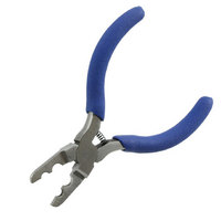
8. USING LOCKING RING PLIERS
The locking ring pliers are used to compress the
retaining ring, allowing installation of the coupling nut
on specific connectors. Use the pliers as follows:
9. REVISION SUMMARY
Per EC 0990–1851–02:
1. Thread the insertion tool into connector
subassembly.
2. Insert the dielectric into insertion tool housing.
3. Place insertion tool plunger into position.
4. Press the plunger until the flange bottoms on
the tool housing.
1. Place retaining ring (and gasket) on connector
housing.
2. Compress the retaining ring with the retaining
ring pliers.
3. Push coupling nut on to housing and over the
retaining ring.
4. Check to make sure the coupling nut rotates
freely after the retaining ring is in place.
S New release of instruction sheet
408–8780
Rev O