1055449-1 Tyco Electronics, 1055449-1 Datasheet - Page 2
1055449-1
Manufacturer Part Number
1055449-1
Description
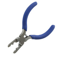
PLIERS RETAINING RING
Manufacturer
Tyco Electronics
Specifications of 1055449-1
Tool Type
Pliers
Product
Accessories
Lead Free Status / RoHS Status
Not applicable / Not applicable
Features
-
Length
-
Tip - Type
-
Lead Free Status / Rohs Status
Lead free / RoHS Compliant


2. DESCRIPTION
Solder Assembly Kit 1055466–1 contains the tooling
required to properly solder SSMA (OSSM) connectors
to semi–rigid and flexible coax cable. The kit contains
a cable fixture sub–assembly, two sets of clamp
inserts for 2.16 [.085] and 1.78 [.070] cable, and four
types of locators that are used to properly align the
connector and cable. The kit also contains a solder
gage for proper spacing of the center contact, a
center contact holder, three dielectric insertion/recess
tools, and locking ring pliers.
The cable fixture subassembly consists of a fixture
frame, thumbscrew, positioning tool and spring. See
Figure 4. When used with the proper clamp inserts
2 of 4
NOTE
1046477–1
1046479–1
1045423–1
1062251–1
1045401–1
1045381–1
1058589–1
1058588–1
1045350–1
1045370–1
1045497–1
1045496–1
1062258–1
1081231–1
1045477–1
1062256–1
1062257–1
1045510–1
1045507–1
Connector Part Number
Connector Part Number
SEMI–RIGID CABLE CONNECTORS
FLEXIBLE CABLE CONNECTORS
Contact customer service or refer to Catalog
1308940 for additional information.
1055670–1
1045422–1
1045410–1
1045351–1
1062250–1
1045369–1
1045481–1
1045482–1
1045476–1
1085817–1
1045511–1
1045508–1
Figure 2
Figure 3
Instruction Sheet
Instruction Sheet
Solder Assembly Kit 1055466–1
408–4776
408–4777
408–4792
408–4793
408–4794
408–4795
408–4796
408–4788
408–4789
408–4790
408–4791
408–4798
408–4799
the assembly holds and locates coaxial cable for
soldering.
3. INSTALLING/REPLACING THE CLAMP INSERT
4. TRIMMING CABLE WITH FIXTURE FRAME
The fixture frame is equipped with six trimming holes
designed to remove the outer jacket and cable
dielectric. The side marked with the number 2 is for
trimming 1.78 [.070], 2.16 [.085], and 3.58 [.141]
cable. See Figures 4 and 5. When cable is fully
bottomed during trimming, a strip length of 2.79 [.110]
will result. If different strip lengths are required the
center conductor must be trimmed separately.
The side marked with a number the number “1” is for
trimming cable already mounted in a connector
housing. See the connector specific instruction sheet
for more information.
5. USING SOLDER GAGE AND CENTER CONTACT
The center contact holder is designed to hold both
male and female center contacts for SSMA (OSSM)
connectors.
The solder gage is used to properly space the SSMA
(OSSM) center contact away from the cable
dielectric.
NOTE
1. Select the appropriate clamp inserts. Refer to
Figure 1 for the appropriate clamp inserts.
2. Remove the cable fixture thumbscrew by
rotating it in a counterclockwise direction.
3. Remove the positioning tool by rotating it in a
counterclockwise direction.
4. Remove the clamp inserts from the frame after
the positioning tool is removed.
5. Sandwich the spring in the pockets on the
replacement clamp inserts.
6. Place clamp inserts in the fixture frame and
reinstall the positioning tool.
7. Retighten positioning tool.
8. Reinstall the thumbscrew.
NOTE
HOLDER
Clamp inserts come in sets of two. Upper and
lower inserts are interchangeable.
Trim blades are NOT included with the kit. Use a
razor blade with .38 [.015] maximum thickness.
408–8780
Rev O