DM180021 Microchip Technology, DM180021 Datasheet - Page 28
DM180021
Manufacturer Part Number
DM180021
Description
KIT STARTER MPLAB FOR PIC18F MCU
Manufacturer
Microchip Technology
Series
MPLAB®r
Type
MCUr
Specifications of DM180021
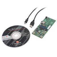
Contents
Board, Cable, CD
Processor To Be Evaluated
PIC18F46J50
Processor Series
PIC18F
Interface Type
SPI
Operating Supply Voltage
3.3 V
Silicon Manufacturer
Microchip
Core Architecture
PIC
Core Sub-architecture
PIC18
Silicon Core Number
PIC18F
Silicon Family Name
PIC18F4xxx
Kit Contents
Board
Lead Free Status / RoHS Status
Lead free / RoHS Compliant
For Use With/related Products
PIC18Fxxxx
Lead Free Status / Rohs Status
Lead free / RoHS Compliant
Available stocks
Company
Part Number
Manufacturer
Quantity
Price
Company:

Part Number:
DM180021
Manufacturer:
Microchip Technology
Quantity:
135
Company:
Part Number:
DM180021
Manufacturer:
MICROCHIP
Quantity:
12 000


MPLAB Starter Kit for PIC18F User’s Guide
4.2
FIGURE 4-2:
DS51852A-page 24
From Host PC
PROGRAMMER/DEBUGGER FUNCTIONAL OVERVIEW
The microcontroller uses one of its A/D Converter channels to sample and convert the
potentiometer’s value to a digital value. Four additional A/D channels are used to
monitor the directional touch pads of S1. The values from these channels are analyzed
with the CTMU to determine when a touch-and-release event occurs on any of the
pads. The application firmware determines which action to take based on the
application’s current context. For example, the capacitive buttons are used as Left and
Right buttons for the USB HID Mouse Demo, while the capacitive slider is used to
emulate the scroll wheel. The capacitive slider is also used by the USB HID Joystick
Demo to generate the Z axes coordinates.
The microcontroller uses the SPI interface to configure the BMA150 acceleration
sensor, then to read 3-axis acceleration and temperature data in digital format. The
acceleration data is used to compute the board’s tilt; this is converted to cursor
movements for the USB HID Mouse Demo and X-Y coordinates for the USB HID
Joystick Demo.
The microcontroller uses the same SPI interface to communicate with the MicroSD
memory card. This allows the USB MSD Card Reader Demo to read and write files to
any MicroSD memory card.
The microcontroller directly drives the OLED display (LED1) using the microcontroller’s
Parallel Master Port (PMP). Data is driven on I/O ports, RD<7:0>. Port control signals,
A0, RD, WR and CS, are provided on ports RB5 and RE<2:0>, respectively. A DC
boost circuit, comprised of power MOSFET Q4 along with D5 and L3, provides the
operating voltage for the OLED.
The microcontroller uses its on-chip USB engine and transceiver to communicate with
the mini-B receptacles on the application side.
Figure 4-2 illustrates the debugging/programming operation of the starter kit.
STARTER KIT PROGRAMMER/DEBUGGER BLOCK DIAGRAM
In its default configuration, the starter kit functions as a USB bus-powered device.
Power is provided via the USB cable; the nominal 5 volt unregulated supply is regulated
by a Microchip MC1727 3.3 volt, Low Dropout (LDO) linear regulator. Proper main
system power is indicated by the green LED (D2).
USB mini-B
Jack
USB Data
Debug
Serial EEPROM
LED
PIC18F67J50
25LC010A
12 MHz
Crystal
SPI
ICSP™
© 2009 Microchip Technology Inc.
To Application Side
(PIC18F46J50)
Related parts for DM180021
Image
Part Number
Description
Manufacturer
Datasheet
Request
R

Part Number:
Description:
Manufacturer:
Microchip Technology Inc.
Datasheet:
Part Number:
Description:
Manufacturer:
Microchip Technology Inc.
Datasheet:
Part Number:
Description:
Manufacturer:
Microchip Technology Inc.
Datasheet:
Part Number:
Description:
Manufacturer:
Microchip Technology Inc.
Datasheet:
Part Number:
Description:
Manufacturer:
Microchip Technology Inc.
Datasheet:
Part Number:
Description:
Manufacturer:
Microchip Technology Inc.
Datasheet:
Part Number:
Description:
Manufacturer:
Microchip Technology Inc.
Datasheet:
Part Number:
Description:
Manufacturer:
Microchip Technology Inc.
Datasheet: