DM180021 Microchip Technology, DM180021 Datasheet - Page 14
DM180021
Manufacturer Part Number
DM180021
Description
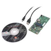
KIT STARTER MPLAB FOR PIC18F MCU
Manufacturer
Microchip Technology
Series
MPLAB®r
Type
MCUr
Specifications of DM180021
Contents
Board, Cable, CD
Processor To Be Evaluated
PIC18F46J50
Processor Series
PIC18F
Interface Type
SPI
Operating Supply Voltage
3.3 V
Silicon Manufacturer
Microchip
Core Architecture
PIC
Core Sub-architecture
PIC18
Silicon Core Number
PIC18F
Silicon Family Name
PIC18F4xxx
Kit Contents
Board
Lead Free Status / RoHS Status
Lead free / RoHS Compliant
For Use With/related Products
PIC18Fxxxx
Lead Free Status / Rohs Status
Lead free / RoHS Compliant
Available stocks
Company
Part Number
Manufacturer
Quantity
Price
Company:

Part Number:
DM180021
Manufacturer:
Microchip Technology
Quantity:
135
Company:
Part Number:
DM180021
Manufacturer:
MICROCHIP
Quantity:
12 000


MPLAB Starter Kit for PIC18F User’s Guide
FIGURE 2-2:
DS51852A-page 10
>>HIDDEMO
File is loading.
Press S1 to load the
PIC18F Starter Kit
CDC_DEMO.HEX
MSD_DEMO.HEX
Please wait.
SD Bootloader
Microchip
9
When the MicroSD bootloader starts, it initializes the capacitive touch routines and the
OLED display. It then monitors for a MicroSD memory card insertion. When an insert
event is detected by the bootloader, the MDD file system is initialized and the file structure
is displayed on the OLED. Note that only folders and HEX files will be displayed.
The user can press the Up and Down buttons to select a specific file or folder. Pressing
the Accept button when a folder is selected causes the bootloader to display the con-
tent of that specific folder on the OLED. To move one level up in the directory hierarchy,
either press the Cancel (Left) button, or press the Accept button when the “..” folder
is selected.
When a HEX file is selected and the Accept (Right) button is pressed, the MicroSD
bootloader will prompt the user for a confirmation to load the file from the MicroSD
memory card and program it to the microcontroller’s Flash memory. After this operation
is finished, the user may choose to execute that application or to remain in the
bootloader.
If the Cancel button is pressed in the root directory, the MicroSD bootloader terminates.
The last application programmed into the microcontroller is then executed.
Figure 2-2 shows a typical sequence of OLED messages from the bootloader
initialization through the loading of an application (read from top left to bottom right).
TYPICAL SEQUENCE FOR BOOTLOADER MESSAGES
2.1.1
The first 40 Kbytes of Flash program memory are used by the MicroSD bootloader.
Figure 2-3 shows the memory map of the PIC18F46J50. The application code must
ensure that the boot area is not overwritten.
2.1.2
Since the hardware Reset and interrupt vectors lie within the boot area, they are
remapped through software to the beginning of the user memory space. Remapping is
simply a branch for interrupts; users may observe an additional latency of two
instruction cycles to handle interrupts.
Memory Organization
Remapped Vectors
file: CUSTOM.HEX
has been loaded.
Press the R button to
start the application
or L button to cancel
Use ‘up’ and ‘down’
Press the ‘accept’
Press menu button to
>>.
Application image
buttons to navigate.
button to select a
file.
continue
..
CUSTOM~1.HEX
JOYSTI~1.HEX
MOUSE ~1.HEX
Please insert a valid
Press Menu to proceed
The following demo
will be loaded:
Press the R button
to accept, or the
L button to cancel
Card not detected!
PIC18F Starter Kit
MicroSD card to
Mouse Demo v1.0
CUSTOM.HEX
© 2009 Microchip Technology Inc.
continue
Related parts for DM180021
Image
Part Number
Description
Manufacturer
Datasheet
Request
R

Part Number:
Description:
Manufacturer:
Microchip Technology Inc.
Datasheet:
Part Number:
Description:
Manufacturer:
Microchip Technology Inc.
Datasheet:
Part Number:
Description:
Manufacturer:
Microchip Technology Inc.
Datasheet:
Part Number:
Description:
Manufacturer:
Microchip Technology Inc.
Datasheet:
Part Number:
Description:
Manufacturer:
Microchip Technology Inc.
Datasheet:
Part Number:
Description:
Manufacturer:
Microchip Technology Inc.
Datasheet:
Part Number:
Description:
Manufacturer:
Microchip Technology Inc.
Datasheet:
Part Number:
Description:
Manufacturer:
Microchip Technology Inc.
Datasheet: