DM180021 Microchip Technology, DM180021 Datasheet - Page 12
DM180021
Manufacturer Part Number
DM180021
Description
KIT STARTER MPLAB FOR PIC18F MCU
Manufacturer
Microchip Technology
Series
MPLAB®r
Type
MCUr
Specifications of DM180021
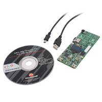
Contents
Board, Cable, CD
Processor To Be Evaluated
PIC18F46J50
Processor Series
PIC18F
Interface Type
SPI
Operating Supply Voltage
3.3 V
Silicon Manufacturer
Microchip
Core Architecture
PIC
Core Sub-architecture
PIC18
Silicon Core Number
PIC18F
Silicon Family Name
PIC18F4xxx
Kit Contents
Board
Lead Free Status / RoHS Status
Lead free / RoHS Compliant
For Use With/related Products
PIC18Fxxxx
Lead Free Status / Rohs Status
Lead free / RoHS Compliant
Available stocks
Company
Part Number
Manufacturer
Quantity
Price
Company:

Part Number:
DM180021
Manufacturer:
Microchip Technology
Quantity:
135
Company:
Part Number:
DM180021
Manufacturer:
MICROCHIP
Quantity:
12 000


MPLAB Starter Kit for PIC18F User’s Guide
DS51852A-page 8
1.3.1
Before connecting the starter kit to any computer for the first time, it is important to install
the accompanying software on the MPLAB Starter Kit for PIC18F CD first. This ensures
that both the MPLAB development environment and C compiler, as well as the relevant
tutorial and help files for the starter kit, are ready to use when the board is connected.
To install the software, insert the starter kit CD into the CD-ROM drive. The installation
process starts automatically. The process pauses for user responses to accept the
Microchip software licenses and to confirm the installation directories; respond
appropriately.
1.3.2
Once the starter kit software is installed, connect the provided USB cable (A to mini-B)
to any available USB port on the PC or powered hub, then to the starter kit at the mini-B
receptacle on the application side of the board (on the right side of the board’s lower
edge, as shown in Figure 1-1). The PC USB connection provides communication and
power to the board. The MicroSD™ Flash card, used to store the demo applications,
may be inserted into the MicroSD slot at any time.
If the cable is connected correctly, the green power LED is lit. The OLED display will
display the “Microchip PIC18F Starter Kit” main menu. At this point, the application waits
for the bootloader Reset switch to be pressed. When it is pressed, the bootloader
application is loaded from the MicroSD card and executed. At this point, you can use the
“Up” and “Down” touch pads to scroll through the available menus, and the “Cancel” and
“Accept” pads to select menu items. Refer to Chapter 2. “The Demonstration
Application” for a complete description of how to use the bootloader application.
When one of the precompiled applications is executed, a sequence of pop-up balloons
in the system tray (lower right of desktop) should appear, stating that (1) new hardware
has been found, (2) drivers are being installed and (3) the new hardware is ready for use.
If you do not see these messages and the starter kit does not work, try unplugging and
reconnecting the USB. If this does not work, refer to Section Chapter 3. “Developing
an Application”.
FIGURE 1-1:
Installing the Software
Connecting the Hardware
STARTER KIT SETUP
MicroSD card
© 2009 Microchip Technology Inc.
A to mini-B USB Cable
Starter Kit
M
Related parts for DM180021
Image
Part Number
Description
Manufacturer
Datasheet
Request
R

Part Number:
Description:
Manufacturer:
Microchip Technology Inc.
Datasheet:
Part Number:
Description:
Manufacturer:
Microchip Technology Inc.
Datasheet:
Part Number:
Description:
Manufacturer:
Microchip Technology Inc.
Datasheet:
Part Number:
Description:
Manufacturer:
Microchip Technology Inc.
Datasheet:
Part Number:
Description:
Manufacturer:
Microchip Technology Inc.
Datasheet:
Part Number:
Description:
Manufacturer:
Microchip Technology Inc.
Datasheet:
Part Number:
Description:
Manufacturer:
Microchip Technology Inc.
Datasheet:
Part Number:
Description:
Manufacturer:
Microchip Technology Inc.
Datasheet: