DK-START-4CGX15N Altera, DK-START-4CGX15N Datasheet - Page 14
DK-START-4CGX15N
Manufacturer Part Number
DK-START-4CGX15N
Description
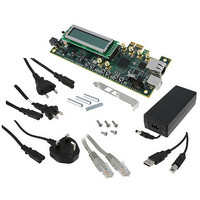
KIT STARTER CYCLONE IV GX
Manufacturer
Altera
Series
Cyclone® IVr
Type
FPGAr
Specifications of DK-START-4CGX15N
Contents
Board, Cables, Power Supply
Silicon Manufacturer
Altera
Core Architecture
FPGA
Core Sub-architecture
Cyclone
Silicon Core Number
EP4C
Silicon Family Name
Cyclone IV GX
Kit Contents
Board, Cables, PSU, CD
Rohs Compliant
Yes
For Use With/related Products
Cyclone IV GX
Lead Free Status / RoHS Status
Lead free / RoHS Compliant
Other names
544-2569
Available stocks
Company
Part Number
Manufacturer
Quantity
Price
Company:

Part Number:
DK-START-4CGX15N
Manufacturer:
Altera
Quantity:
135


4–2
Factory Default Switch Settings
Table 4–1. S8 Dip Switch Settings
Cyclone IV GX Transceiver Starter Kit User Guide
1
2
3
4
Switch
CLKSEL
USER_PGM
MAX_JTAG_EN
PCIE_JTAG_EN
Board
Label
This section shows the factory switch settings for the Cyclone IV GX transceiver
starter board.
switch on the bottom side of the board.
Figure 4–1. Switch Locations and Default Settings on the Board Bottom
To restore the switches to their factory default settings, perform the following steps:
1. Set DIP switch bank (S8) to match
2. Set DIP switch bank (S7) to match
Switch 1 has the following options:
■
■
Switch 2 has the following options:
■
■
Switch 3 has the following options:
■
■
Switch 4 has the following options:
■
■
When on, the onboard clock is used for the FPGA differential clock inputs.
When off, the differential SMA clock is used for the FPGA differential clock
inputs.
When on, the PFL loads the user hardware 1 design on power up.
When off, the PFL loads the factory design on power up.
When on, the MAX II EPM2210 device is removed from the JTAG chain.
When off, the MAX II EPM2210 device is included in the JTAG chain.
When on, the PCIe device is in removed from JTAG chain.
When off, the PCIe device is included in the JTAG chain.
Figure 4–1
ON
1
S8
2
3
shows the switch locations and the default position of each
4
OFF = 1
ON = 0
Function
ON
1
Table 4–1
Table 4–2
S7
2
3
4
ON = 0
OFF = 1
and
and
Figure
Figure
4–1.
4–1.
© March 2010 Altera Corporation
Factory Default Switch Settings
Chapter 4: Board Setup
Position
Default
Off
Off
On
On
Related parts for DK-START-4CGX15N
Image
Part Number
Description
Manufacturer
Datasheet
Request
R

Part Number:
Description:
KIT STARTER CYCLONE III EP3C25
Manufacturer:
Altera
Datasheet:

Part Number:
Description:
Cyclone IV Tranceiver Development Kit
Manufacturer:
Altera
Datasheet:

Part Number:
Description:
Programmable Logic IC Development Tools FPGA Development Kit For 5AGXFB3H4F35C5N
Manufacturer:
Altera Corporation
Datasheet:
Part Number:
Description:
Programmable Logic IC Development Tools FPGA Starter Kit For 5AGXFB3H4F
Manufacturer:
Altera Corporation
Datasheet:

Part Number:
Description:
CYCLONE II STARTER KIT EP2C20N
Manufacturer:
Altera
Datasheet:

Part Number:
Description:
CPLD, EP610 Family, ECMOS Process, 300 Gates, 16 Macro Cells, 16 Reg., 16 User I/Os, 5V Supply, 35 Speed Grade, 24DIP
Manufacturer:
Altera Corporation
Datasheet:
Part Number:
Description:
CPLD, EP610 Family, ECMOS Process, 300 Gates, 16 Macro Cells, 16 Reg., 16 User I/Os, 5V Supply, 15 Speed Grade, 24DIP
Manufacturer:
Altera Corporation
Datasheet:
Part Number:
Description:
Manufacturer:
Altera Corporation
Datasheet:
Part Number:
Description:
CPLD, EP610 Family, ECMOS Process, 300 Gates, 16 Macro Cells, 16 Reg., 16 User I/Os, 5V Supply, 30 Speed Grade, 24DIP
Manufacturer:
Altera Corporation
Datasheet:
Part Number:
Description:
High-performance, low-power erasable programmable logic devices with 8 macrocells, 10ns
Manufacturer:
Altera Corporation
Datasheet:
Part Number:
Description:
High-performance, low-power erasable programmable logic devices with 8 macrocells, 7ns
Manufacturer:
Altera Corporation
Datasheet:
Part Number:
Description:
Classic EPLD
Manufacturer:
Altera Corporation
Datasheet:
Part Number:
Description:
High-performance, low-power erasable programmable logic devices with 8 macrocells, 10ns
Manufacturer:
Altera Corporation
Datasheet: