AS5030 AB austriamicrosystems, AS5030 AB Datasheet - Page 3
AS5030 AB
Manufacturer Part Number
AS5030 AB
Description
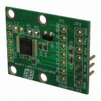
BOARD ADAPTER AS5030
Manufacturer
austriamicrosystems
Specifications of AS5030 AB
Sensor Type
Magnetic, Rotary Position
Sensing Range
360°
Interface
Serial
Voltage - Supply
5V
Embedded
No
Utilized Ic / Part
AS5030
Lead Free Status / RoHS Status
Lead free by exemption / RoHS compliant by exemption
Sensitivity
-


AS5030 8-bit Programmable Magnetic Rotary Encoder
Adapterboard Operation Manual
3 AS5030 and adapter board pinout
Table 1: Pin description
Pin types: S:
Revision 1.0, 26.February 2009
Pin#
Board
JP1 - 1
JP1 - 2
JP1 - 3
JP1 - 4
JP1 - 5
JP1 - 6
JP1 - 7
JP2 - 1
JP2 - 2
JP2 - 3
JP2 - 4
JP2 - 5
JP2 - 6
JP2 - 7
JP3 - 1
JP3 - 2
JP3 - 3
JP3 - 4
JP3 - 5
P1
bridge
P2
bridge
Pin#
AS5030
3
13
10
11
12
-
2
3
13
-
9
16
1
3
7
6
5
4
3
14
15
DI_ST: digital input / Schmitt-Trigger
DIO:
GND Mag PWM DX
Prog
bi-directional digital pin
supply pin
P2
P1
AS5030-AB-2.0
GND SINn SIN COSn
DI
Symbol
GND
5V
CLK
CS
DIO
DI
PROG
GND
5V
Analog
DX
PWM
MagRNG
GND
COS
COSn
SIN
SINn
GND
C1
C2
DIO
AS5030
CS
Ana
CLK
COS
5V
5V
Figure 3: AS5030 adapter board connectors and encoder pinout
Type
S
S
DI_ST
DI_ST
DIO
DI
S
S
S
-
DO
DO
DO_T
S
-
-
-
-
S
DI
DI
GND
GND
www.austriamicrosystems.com
Supply ground
OTP Programming voltage supply pin. Leave open or connect to VDD if not used
Supply ground
Supply ground
Description
Positive supply voltage, 4.5V to 5.5V
Clock Input of Synchronous Serial Interface; Schmitt-Trigger input
Chip Select for serial data transmission, active high; Schmitt-Trigger input,
external pull-down resistor (~50kΩ) required in read-only mode
Data output / command input for digital serial interface
Command input for digital serial interface. Connect to GND if not used.
Positive supply voltage, 4.5V to 5.5V
0~5V analog output. Generated by the PWM output and filtered.
Digital output for 2-wire operation and Daisy Chain mode
Pulse Width Modulation output, 2.26µs pulse width per step (2.26µs ~ 512µs)
Push-Pull output. Is HIGH when the magnetic field strength is too weak, e.g. due to missing
magnet
Must be left unconnected for normal operation. COS output in SIN/COS mode (P1 open)
Must be left unconnected for normal operation. COSn output in SIN/COS mode (P1 open)
Must be left unconnected for normal operation. SIN output in SIN/COS mode (P1 open)
Must be left unconnected for normal operation. SINn output in SIN/COS mode (P1 open)
Supply ground
Configuration input for Sin/Cos output:
-
-
This pin is scanned at power-on-reset and at wakeup from one of the Ultra Low Power Modes
Configuration input for serial wire mode:
-
-
This pin is scanned at power-on-reset and at wakeup from one of the Ultra Low Power Modes
Connect to VSS for normal operation (P1 closed, by default)
High level (P1 open) to enable Sin/Cos outputs
Connect to VSS for 3-wire operation (P2 closed, by default)
High level (P2 open) for 2-wire operation
DO:
DO_T:
DI:
digital output
digital output / tri-state
digital input (standard CMOS; no pull-up or pull-down)
Page 3 of 10
Related parts for AS5030 AB
Image
Part Number
Description
Manufacturer
Datasheet
Request
R

Part Number:
Description:
IC ENCODER ROTARY 8-BIT 16-TSSOP
Manufacturer:
austriamicrosystems
Datasheet:

Part Number:
Description:
BOARD DEMO AS5030
Manufacturer:
austriamicrosystems
Datasheet:
Part Number:
Description:
IC ENCODER ROTARY 8-BIT 16-TSSOP
Manufacturer:
austriamicrosystems
Datasheet:
Part Number:
Description:
8-bit High-speed Absolute Magnetic Rotary Encoder
Manufacturer:
austriamicrosystems
Datasheet:
Part Number:
Description:
IC SWITCH QUAD SPST 14-TSSOP
Manufacturer:
austriamicrosystems
Datasheet:
Part Number:
Description:
IC SWITCH QUAD SPST 14-TSSOP
Manufacturer:
austriamicrosystems
Datasheet:
Part Number:
Description:
IC AMP AUDIO MONO 1.8W 10-MSOP
Manufacturer:
austriamicrosystems
Datasheet:
Part Number:
Description:
IC AMP AUDIO MONO 1.8W 10-MSOP
Manufacturer:
austriamicrosystems
Datasheet:
Part Number:
Description:
IC AMP AUDIO MONO 1.8W 10-MSOP
Manufacturer:
austriamicrosystems
Datasheet:
Part Number:
Description:
IC AMP AUD 1.8W 3DB GAIN 10-MSOP
Manufacturer:
austriamicrosystems
Datasheet:
Part Number:
Description:
IC DRIVER LED 8-DIGIT 24-SOIC
Manufacturer:
austriamicrosystems
Datasheet:
Part Number:
Description:
IC DRIVER LED 8-DIGIT 24-SOIC
Manufacturer:
austriamicrosystems
Datasheet:
Part Number:
Description:
IC, LINE/SPEAKER PHONE CIRCUIT, SOIC-28
Manufacturer:
austriamicrosystems
Datasheet:
Part Number:
Description:
IC MULTI-STANDARD CMOS TELEPHONE SOIC-28
Manufacturer:
austriamicrosystems
Datasheet:
Part Number:
Description:
IC MULTI-STANDARD CMOS TELEPHONE SOIC-28
Manufacturer:
austriamicrosystems
Datasheet: