DEMOMPR083 Freescale Semiconductor, DEMOMPR083 Datasheet - Page 15
DEMOMPR083
Manufacturer Part Number
DEMOMPR083
Description
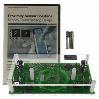
BOARD DEMO FOR MPR083 CTLR
Manufacturer
Freescale Semiconductor
Specifications of DEMOMPR083
Sensor Type
Touch, Capacitive
Sensing Range
8 Buttons/Keys
Interface
I²C
Voltage - Supply
1.8 V ~ 3.6 V
Embedded
Yes, MCU, 8-Bit
Utilized Ic / Part
MPR083
Operating Voltage
1.8 V to 3.6 V
Maximum Operating Temperature
+ 85 C
Minimum Operating Temperature
- 40 C
Operating Current
41 uA
Lead Free Status / RoHS Status
Contains lead / RoHS non-compliant
Sensitivity
-
Lead Free Status / Rohs Status
Lead free / RoHS Compliant
For Use With/related Products
MPR083


Sensors
Freescale Semiconductor
5
5.1
The MPR083 features a Low Power mode that can reduce the power consumption into the microamps range. This feature can
be used to both adjust the response time of the system, and change the conditions on which Low Power would be enabled.
5.2
This Low Power configuration is only active when the sensor controller is in Run2 mode. The Low Power mode decreases current
consumption by increasing the response time of the MPR083. This increase is controlled through two factors.
During normal Run2 operation of the sensor controller the Max Response Time (MRT) is calculated by taking the product of the
TASP and the primary clock. From Chapter 4 the primary clock is the (MTP + 5) ms. Since the sensor controller is in Run2, the
primary clock is also multiplied by a factor of 8. The debounce rate of the MPR083 is 4 times the sample rate thus the MRT is
represented by the following equation.
First, the Idle Interface Timeout (IIT) represents the total time the touch interface should remain idle before going into Low Power
mode. This value can be calculated by taking the product of the ITP, TASP and primary clock (8ms) with a factor of 64. Thus the
IIT is represented as follows:
Second, the Max Response Time (MRT) represents the total time the touch interface should remain inactive before scanning the
electrodes. This value can be calculated by taking the product of the SCD, TASP and primary clock (8ms) with a factor of 5. Thus
the MRT is represented as follows:
When in Run2 mode, the sensor controller will initially scan the electrodes at the rate of MRT
touch interface remains idle for the IIT period then the scan period will change to MRT
detected the scan rate will transition back to MRT
Low Power Configuration
Introduction
Operation
MRT
run2 SET
ITT
MRT
2
=
=
Figure 18. Low Power Scan Period Transition Diagram
1
MTP
--------------------- -
=
MTP
--------------------- -
8
MTP
--------------------- -
8
+
+
5
8
5
1
+
+
.
+
LP DISABLED
1
5
1
MRT 1
+
1
TASP ITP
TASP SCD 4 8
TASP 4 8ms
TOUCH DETECTED
ITT PERIOD
6 8ms
ms
2
. When scanning at MRT
MRT 2
1
. When scanning at MRT
2
and a touch is
Equation 1
Equation 2
Equation 3
1
MPR083
and the
15
Related parts for DEMOMPR083
Image
Part Number
Description
Manufacturer
Datasheet
Request
R

Part Number:
Description:
Manufacturer:
STMicroelectronics
Datasheet:

Part Number:
Description:
DEMO BOARD FOR HMC6042/HMC1041Z
Manufacturer:
Honeywell Microelectronics & Precision Sensors

Part Number:
Description:
DEMO BOARD FOR HMC1042L/HMC1041Z
Manufacturer:
Honeywell Microelectronics & Precision Sensors
Datasheet:

Part Number:
Description:
KIT DEMO 4 SENSOR CHAN RS232
Manufacturer:
VTI Technologies
Datasheet:


Part Number:
Description:
DEMO: DC Power Supply, 32 Volts, 3 Amps
Manufacturer:
Tektronix
Part Number:
Description:
DEMO: Programmable DC Power Supply, 32 Volts, 3 Amps
Manufacturer:
Tektronix

Part Number:
Description:
Manufacturer:
Freescale Semiconductor, Inc
Datasheet:
Part Number:
Description:
Manufacturer:
Freescale Semiconductor, Inc
Datasheet:
Part Number:
Description:
Manufacturer:
Freescale Semiconductor, Inc
Datasheet:
Part Number:
Description:
Manufacturer:
Freescale Semiconductor, Inc
Datasheet:
Part Number:
Description:
Manufacturer:
Freescale Semiconductor, Inc
Datasheet:
Part Number:
Description:
Manufacturer:
Freescale Semiconductor, Inc
Datasheet:
Part Number:
Description:
Manufacturer:
Freescale Semiconductor, Inc
Datasheet:
Part Number:
Description:
Manufacturer:
Freescale Semiconductor, Inc
Datasheet: