STEVAL-ISA026V1 STMicroelectronics, STEVAL-ISA026V1 Datasheet - Page 8
STEVAL-ISA026V1
Manufacturer Part Number
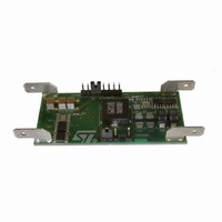
STEVAL-ISA026V1
Description
EVAL BOARD 20A 250KHZ L6732
Manufacturer
STMicroelectronics
Type
DC/DC Switching Converters, Regulators & Controllersr
Specifications of STEVAL-ISA026V1
Design Resources
STEVAL-ISA026V1 Gerber Files STEVAL-ISA026V1 Schematic STEVAL-ISA026V1 Bill of Material
Main Purpose
DC/DC, Step Down
Outputs And Type
1, Non-Isolated
Voltage - Output
3.3V
Current - Output
20A
Voltage - Input
4.5 ~ 14V
Regulator Topology
Buck
Frequency - Switching
250kHz
Board Type
Fully Populated
Utilized Ic / Part
L6732
Input Voltage
4.5 V to 14 V
Output Voltage
3.3 V
Product
Power Management Modules
Silicon Manufacturer
ST Micro
Silicon Core Number
L6732
Kit Application Type
Power Management - Voltage Regulator
Rohs Compliant
No
Lead Free Status / RoHS Status
Lead free / RoHS Compliant
Power - Output
-
Lead Free Status / Rohs Status
Lead free / RoHS Compliant
For Use With/related Products
L6732
Other names
497-5869
Available stocks
Company
Part Number
Manufacturer
Quantity
Price
Company:

Part Number:
STEVAL-ISA026V1
Manufacturer:
STMicroelectronics
Quantity:
135


Pin connection and function
8/37
Table 4.
Pin n.
10
11
12
13
14
15
16
7
8
9
Pin functions (continued)
EAREF
PHASE
HGATE
LGATE
V
PGND
Name
BOOT
OCH
OCL
V
CCDR
CC
By setting the voltage at this pin is possible to select the internal/external
reference and the switching frequency:
V
V
V
An internal clamp limits the maximum V
captures the analog value present at this pin at the start-up when V
meets the UVLO threshold.
A resistor connected from this pin to ground sets the valley- current-limit.
The valley current is sensed through the low-side MOSFET(s). The internal
current generator sources a current of 100 µA (I
through the external resistor (R
the following equation:
Connecting a capacitor from this pin to GND helps in reducing the noise
injected from V
high-frequency noise related to the GND. Connect a capacitor only to a
“clean” GND.
A resistor connected from this pin and the high-side MOSFET(s) drain sets
the peak-current-limit. The peak current is sensed through the high-side
MOSFET(s). The internal 100 µA current generator (I
from the drain through the external resistor (R
threshold is given by the following equation:
This pin is connected to the source of the high-side MOSFET(s) and
provides the return path for the high-side driver. This pin monitors the drop
across both the upper and lower MOSFET(s) for the current limit together
with OCH and OCL.
This pin is connected to the high-side MOSFET(s) gate.
Through this pin is supplied the high-side driver. Connect a capacitor from
this pin to the PHASE pin and a diode from V
versus BOOT).
This pin has to be connected closely to the low-side MOSFET(s) source in
order to reduce the noise injection into the device.
This pin is connected to the low-side MOSFET(s) gate.
5 V internally regulated voltage. It is used to supply the internal drivers.
Filter it to ground with at least 1 µF ceramic cap.
Supply voltage pin.
The operative supply voltage range is from 4.5 V to 14 V.
EAREF
EAREF
EAREF
= 80 %-95 % of V
0-80 % of V
= 95 %-100 % of V
CC
to the device, but can be a low impedance path for the
CCDR
I
CCDR
VALLEY
-> external reference/F
I
PEAK
CCDR ->
OCL
-> V
Function
=
=
). The over-current threshold is given by
V
REF
I
--------------------------------- -
OCH
REF
--------------------------------- -
2 R
I
R
OCL
•
DSONHS
EAREF
= 0.6 V/F
= 0.6 V/F
•
DSONLS
•
R
R
OCH
CCDR
OCL
OCH
at 2.5 V (typ.). The device
OCL
SW
SW
). The over-current
SW
) from this pin to ground
to this pin (cathode
= 250 kHz
= 500 kHz
OCH
= 250 kHz
) sinks a current
CC
L6732
Related parts for STEVAL-ISA026V1
Image
Part Number
Description
Manufacturer
Datasheet
Request
R

Part Number:
Description:
BOARD RGB CTR ST7,STP08C596MTR
Manufacturer:
STMicroelectronics
Datasheet:

Part Number:
Description:
Power Management IC Development Tools Full Speed USB to RS232 Bridge Demo
Manufacturer:
STMicroelectronics
Datasheet:
Part Number:
Description:
Power Management IC Development Tools 2.5W solar eval BRD USB SPV1040 LD39050
Manufacturer:
STMicroelectronics
Datasheet:

Part Number:
Description:
BOARD EVAL FOR MEMS SENSORS
Manufacturer:
STMicroelectronics
Datasheet:

Part Number:
Description:
KIT DEV STARTER ST10F276Z5
Manufacturer:
STMicroelectronics
Datasheet:

Part Number:
Description:
BOARD EVAL HDMI $ VIDEO SWITCH
Manufacturer:
STMicroelectronics
Datasheet:

Part Number:
Description:
BOARD DEMO ACCELEROMETER DIL24
Manufacturer:
STMicroelectronics
Datasheet:

Part Number:
Description:
BOARD STLM75/STDS75/ST72F651
Manufacturer:
STMicroelectronics
Datasheet:

Part Number:
Description:
EVAL BOARD 3AXIS MEMS ACCELLRMTR
Manufacturer:
STMicroelectronics
Datasheet:

Part Number:
Description:
BOARD EVAL 8BIT MICRO + TDE1708
Manufacturer:
STMicroelectronics
Datasheet:
Part Number:
Description:
STMicroelectronics [RIPPLE-CARRY BINARY COUNTER/DIVIDERS]
Manufacturer:
STMicroelectronics
Datasheet:
Part Number:
Description:
STMicroelectronics [LIQUID-CRYSTAL DISPLAY DRIVERS]
Manufacturer:
STMicroelectronics
Datasheet:
Part Number:
Description:
BOARD EVAL FOR MEMS SENSORS
Manufacturer:
STMicroelectronics
Datasheet: