KSZ8001L-EVAL Micrel Inc, KSZ8001L-EVAL Datasheet - Page 22
KSZ8001L-EVAL
Manufacturer Part Number
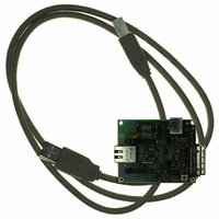
KSZ8001L-EVAL
Description
BOARD EVALUATION FOR KSZ8001L
Manufacturer
Micrel Inc
Datasheet
1.KSZ8001S.pdf
(46 pages)
Specifications of KSZ8001L-EVAL
Main Purpose
Interface, Ethernet PHY
Embedded
No
Utilized Ic / Part
KSZ8001L
Primary Attributes
Single Chip PHY, 100BASE-TX/100BASE-FX/10BASE-T
Secondary Attributes
MII, RMII, SMII, HP Auto MDI, MDI-X Auto Polarity Correction, LinkMD
Lead Free Status / RoHS Status
Lead free / RoHS Compliant
Other names
576-1620


March 2006
Micrel
Auto MDI/MDI-X Cross-Over Transformer Connection
KSZ8001 features HP Auto MDI/MDI-X crossover and requires symmetric transformers that support Auto MDI/MDI-X.
“Selection of Isolation Transformer” for a list of transformers that support Auto MDI/MDI-X.
Power Management
The KSZ8001 offers the following modes for power management:
100BASE-FX Mode
100BASE-FX mode is activated when FXSD/FXEN is higher than 0.6V (This pin has a default pull down). Under this mode, the auto-
negotiation and auto-MDIX features are disabled.
In fiber operation FXSD pin should connect to the SD (signal detect) output of the fiber module. The internal threshold of FXSD is
around
summarized in the following table:
To ensure proper operation, the swing of fiber module SD should cover the threshold variation. A resistive voltage divider is
recommended to adjust the SD voltage range.
FEF (Far End Fault), repetition of a special pattern, which consists of 84-ones and 1-zero, is generated under “FX mode with no
signal detected”. The purpose of FEF is to notify the sender of a faulty link. When receiving a FEF, the LINK will go down to indicate
a fault, even with fiber signal detected. The transmitter is not affected by receiving a FEF and still sends out its normal transmit
pattern from MAC. FEF can be disabled by strapping pin27 low, please refer to “Strapping Options” section.
Media Converter Operation
The KSZ8001 is capable of performing media conversion with 2 parts in a back-to-back RMII mode as indicated in the diagram. Both
parts are in RMII mode and with RMII_BTB asserted (pin21 & 22 strapped high). One part is operating at TX mode and the other in
FX mode. Both parts can share a common 50MHz oscillator.
Under this operation, auto-Negotiation on the TX side will prohibit 10BASE-T link up. Additional options can be implemented under
this operation. Disable the transmitter and set it at tri-state by controlling the high TXD2 pin. In order to do this, RXD2 and TXD2 pins
need to be connected via an inverter. When TXD2 pin is high in both the copper and fiber operation, it disables transmit. Meanwhile,
the RXD2 pin on the copper side serves as the energy detect and can indicate if a line signal is detected. TXD3 should be tied low
and RXD3 let float. Please contact your local Micrel FAE for a Media Converter reference design.
FXSD/FXEN
Less than 0.6V
Less than 2.15V,
but greater than 0.6V
Greater than 2.25V
•
•
⅔
Power Down Mode: This mode can be achieved by writing to Register 0.11 or pulling pin 30 PD# Low. In the power down
state, the KS8061 disables all internal functions and drives output pins to logic zero, except for the MII serial management
interface.
Power Saving Mode: writing to register 1fh.10 can disable this mode. The KSZ8001 will then turn off everything except for
the Energy Detect and PLL circuits when the cable is not installed. In other words, the KSZ8001 will shutdown most of the
internal circuits to save power if there is no link. Power Saving mode will be in this most effective state when Auto-
Negotiation Mode is enabled.
Vdd +/- 50 mV (2.2V +/- 0.05V at 3.3V). Above this level, it is considered Fiber signal detected, and the operation is
100TX mode
FX mode
No signal detected
FEF generated
Signal detected
Condition
FX mode
22
Revision 1.03
KSZ8001
See
Related parts for KSZ8001L-EVAL
Image
Part Number
Description
Manufacturer
Datasheet
Request
R

Part Number:
Description:
IC TXRX PHY 10/100 3.3V 48-LQFP
Manufacturer:
Micrel Inc
Datasheet:
Part Number:
Description:
10/100 BASE-TX/FX Physical Layer Transceiver With LinkMD Cable Diagnostics, Single 3.3V Supply, 48-LQFP,
Manufacturer:
Micrel Inc
Datasheet:

Part Number:
Description:
Manufacturer:
Micrel Inc
Datasheet:
Part Number:
Description:
Manufacturer:
Micrel Inc
Datasheet:

Part Number:
Description:
Manufacturer:
Micrel Inc
Datasheet:
Part Number:
Description:
Manufacturer:
Micrel Inc
Datasheet:
Part Number:
Description:
Manufacturer:
Micrel Inc
Datasheet:
Part Number:
Description:
Manufacturer:
Micrel Inc
Datasheet:
Part Number:
Description:
Manufacturer:
Micrel Inc
Datasheet:
Part Number:
Description:
Manufacturer:
Micrel Inc
Datasheet:
Part Number:
Description:
Manufacturer:
Micrel Inc
Datasheet:
Part Number:
Description:
Manufacturer:
Micrel Inc
Datasheet:
Part Number:
Description:
Manufacturer:
Micrel Inc
Datasheet:
Part Number:
Description:
Manufacturer:
Micrel Inc
Datasheet: