CDB42448 Cirrus Logic Inc, CDB42448 Datasheet - Page 46
CDB42448
Manufacturer Part Number
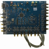
CDB42448
Description
BOARD EVAL FOR CS42448 CODEC
Manufacturer
Cirrus Logic Inc
Specifications of CDB42448
Main Purpose
Audio, CODEC
Embedded
Yes, FPGA / CPLD
Utilized Ic / Part
CS42448
Primary Attributes
24-Bit, 192 kHz, 6 ADCs: 102dB Dynamic Range, 8 DACs: 105dB Dynamic Range
Secondary Attributes
Time Division Multiplexed (TDM), I2C, and SPI Interface, Popguard® Technology
Description/function
Audio CODECs
Operating Supply Voltage
5 V to 12 V
Product
Audio Modules
For Use With/related Products
CS42448
Lead Free Status / RoHS Status
Contains lead / RoHS non-compliant
Lead Free Status / RoHS Status
Lead free / RoHS Compliant, Contains lead / RoHS non-compliant
Other names
598-1151


46
6.6.2
6.6.3
6.6.4
6.6.5
ADC3 High Pass Filter Freeze (ADC3_HPF FREEZE)
Default = 0
Function:
When this bit is set, the internal high-pass filter will be disabled for ADC3.The current DC offset value will
be frozen and continue to be subtracted from the conversion result. See
tics” on page
DAC De-Emphasis Control (DAC_DEM)
Default = 0
0 - No De-Emphasis
1 - De-Emphasis Enabled (Auto-Detect Fs)
Function:
Enables the digital filter to maintain the standard 15μs/50μs digital de-emphasis filter response at the
auto-detected sample rate of either 32, 44.1, or 48 kHz. De-emphasis will not be enabled, regardless of
this register setting, at any other sample rate.
ADC1 Single-Ended Mode (ADC1 SINGLE)
Default = 0
0 - Disabled; Differential input to ADC1
1 - Enabled; Single-Ended input to ADC1
Function:
When enabled, this bit allows the user to apply a single-ended input to the positive terminal of ADC1. A
+6 dB digital gain is automatically applied to the serial audio data of ADC1. The negative leg must be driv-
en to the common mode of the ADC. See
ADC2 Single-Ended Mode (ADC2 SINGLE)
Default = 0
0 - Disabled; Differential input to ADC2
1 - Enabled; Single-Ended input to ADC2
Function:
When enabled, this bit allows the user to apply a single-ended input to the positive terminal of ADC2. A
+6 dB digital gain is automatically applied to the serial audio data of ADC2. The negative leg must be driv-
en to the common mode of the ADC. See
13.
Figure 27 on page 53
Figure 27 on page 53
for a graphical description.
for a graphical description.
“ADC Digital Filter Characteris-
CS42448
DS648F3
Related parts for CDB42448
Image
Part Number
Description
Manufacturer
Datasheet
Request
R

Part Number:
Description:
Development Kit
Manufacturer:
Cirrus Logic Inc
Datasheet:
Part Number:
Description:
Development Kit
Manufacturer:
Cirrus Logic Inc
Datasheet:


Part Number:
Description:
High-efficiency PFC + Fluorescent Lamp Driver Reference Design
Manufacturer:
Cirrus Logic Inc
Datasheet:
Part Number:
Description:
Development Kit
Manufacturer:
Cirrus Logic Inc
Datasheet:
Part Number:
Description:
Development Kit
Manufacturer:
Cirrus Logic Inc
Datasheet:

Part Number:
Description:
Development Kit
Manufacturer:
Cirrus Logic Inc
Datasheet:
Part Number:
Description:
Development Kit
Manufacturer:
Cirrus Logic Inc
Datasheet:
Part Number:
Description:
Development Kit
Manufacturer:
Cirrus Logic Inc
Datasheet:
Part Number:
Description:
Development Kit
Manufacturer:
Cirrus Logic Inc
Datasheet:

Part Number:
Description:
EVALUATION BOARD FOR CS8427
Manufacturer:
Cirrus Logic Inc
Datasheet:

Part Number:
Description:
BOARD EVAL FOR CS8416 RCVR
Manufacturer:
Cirrus Logic Inc
Datasheet:

Part Number:
Description:
EVALUATION BOARD FOR CS8420
Manufacturer:
Cirrus Logic Inc
Datasheet:

Part Number:
Description:
KIT DEVELOPMENT EP9315 ARM9
Manufacturer:
Cirrus Logic Inc
Datasheet:

Part Number:
Description:
KIT DEVELOPMENT EP9302 ARM9
Manufacturer:
Cirrus Logic Inc
Datasheet: