AD9516-4/PCBZ Analog Devices Inc, AD9516-4/PCBZ Datasheet - Page 64
AD9516-4/PCBZ
Manufacturer Part Number
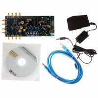
AD9516-4/PCBZ
Description
BOARD EVAL FOR AD9516-4 1.8GHZ
Manufacturer
Analog Devices Inc
Specifications of AD9516-4/PCBZ
Main Purpose
Timing, Clock Generator
Embedded
No
Utilized Ic / Part
AD9516-4
Primary Attributes
2 Inputs, 14 Outputs, 1.6GHz VCO
Secondary Attributes
CMOS, LVDS, LVPECL Output Logic, ADIsimCLK™ Graphical User Interface
Silicon Manufacturer
Analog Devices
Application Sub Type
PLL Clock Synthesizer
Kit Application Type
Clock & Timing
Silicon Core Number
AD9516-0, AD9516-1, AD9516-2
Silicon Family Name
AD9516-X
Rohs Compliant
Yes
Lead Free Status / RoHS Status
Lead free / RoHS Compliant


AD9516-4
Reg.
Addr.
(Hex)
0x01B
0x01C
Bits
[4:0]
7
6
5
4
3
2
1
0
Name
REFMON
pin control
Disable
switchover
deglitch
Select REF2
Use REF_SEL pin
Reserved
Reserved
REF2 power-on
REF1 power-on
Differential
reference
Description
Selects the signal that is connected to the REFMON pin.
4
0
0
0
0
0
0
0
0
0
0
0
0
0
0
0
0
1
1
1
1
1
1
1
1
1
1
1
1
1
1
1
1
Disables or enables the switchover deglitch circuit.
0: enables switchover deglitch circuit (default).
1: disables switchover deglitch circuit.
If Register 0x01C, Bit 5 = 0, select reference for PLL.
0: selects REF1 (default).
1: selects REF2.
Sets method of PLL reference selection.
0: uses Register 0x01C, Bit 6 (default).
1: uses REF_SEL pin.
0: (default).
0: (default).
This bit turns the REF2 power on.
0: REF2 power off (default).
1: REF2 power on.
This bit turns the REF1 power on.
0: REF1 power off (default).
1: REF1 power on.
Selects the PLL reference mode, differential or single-ended. Single-ended must be selected for the automatic
switchover or REF1 and REF2 to work.
0: single-ended reference mode (default).
1: differential reference mode.
3
0
0
0
0
0
0
0
0
1
1
1
1
1
1
1
1
0
0
0
0
0
0
0
0
1
1
1
1
1
1
1
1
2
0
0
0
0
1
1
1
1
0
0
0
0
1
1
1
1
0
0
0
0
1
1
1
1
0
0
0
0
1
1
1
1
1
0
0
1
1
0
0
1
1
0
0
1
1
0
0
1
1
0
0
1
1
0
0
1
1
0
0
1
1
0
0
1
1
0
0
1
0
1
0
1
0
1
0
1
0
1
0
1
0
1
0
1
0
1
0
1
0
1
0
1
0
1
0
1
0
1
Level or
Dynamic
Signal
LVL
DYN
DYN
DYN
DYN
LVL
LVL
LVL
LVL
LVL
LVL
LVL
LVL
LVL
LVL
LVL
LVL
DYN
DYN
DYN
DYN
LVL
LVL
LVL
LVL
LVL
LVL
LVL
LVL
LVL
LVL
LVL
Rev. A | Page 64 of 80
Signal at REFMON Pin
Ground (dc) (default).
REF1 clock (differential reference when in differential mode).
REF2 clock (not available in differential mode).
Selected reference to PLL (differential reference when in differential mode).
Unselected reference to PLL (not available in differential mode).
Status of selected reference (status of differential reference); active high.
Status of unselected reference (not available in differential mode); active high.
Status REF1 frequency (active high).
Status REF2 frequency (active high).
(Status REF1 frequency) AND (status REF2 frequency).
(DLD) AND (status of selected reference) AND (status of VCO).
Status of VCO frequency (active high).
Selected reference (low = REF1, high = REF2).
Digital lock detect (DLD); active low.
Holdover active (active high).
LD pin comparator output (active high).
VS (PLL supply).
REF1 clock (differential reference when in differential mode).
REF2 clock (not available in differential mode).
Selected reference to PLL (differential reference when in differential mode).
Unselected reference to PLL (not available when in differential mode).
Status of selected reference (status of differential reference); active low.
Status of unselected reference (not available in differential mode); active low.
Status of REF1 frequency (active low).
Status of REF2 frequency (active low).
(Status of REF1 frequency) AND (Status of REF2 frequency) .
(DLD) AND (Status of selected reference) AND (Status of VCO) .
Status of VCO frequency (active low).
Selected reference (low = REF2, high = REF1).
Digital lock detect (DLD); active low.
Holdover active (active low).
LD pin comparator output (active low).
Related parts for AD9516-4/PCBZ
Image
Part Number
Description
Manufacturer
Datasheet
Request
R

Part Number:
Description:
IC CLOCK PLL/VCO 2GHZ 64LFCSP
Manufacturer:
Analog Devices Inc
Datasheet:
Part Number:
Description:
IC CLOCK GEN 2.8GHZ VCO 64-LFCSP
Manufacturer:
Analog Devices Inc
Datasheet:
Part Number:
Description:
IC,Fourteen Distributed-Output Clock Driver,LLCC,64PIN,PLASTIC
Manufacturer:
Analog Devices Inc
Datasheet:
Part Number:
Description:
IC,Ten Distributed-Output Clock Driver,LLCC,64PIN,PLASTIC
Manufacturer:
Analog Devices Inc
Datasheet:
Part Number:
Description:
IC,Ten Distributed-Output Clock Driver,LLCC,64PIN,PLASTIC
Manufacturer:
Analog Devices Inc
Datasheet:
Part Number:
Description:
Clock IC With 1.8GHz On-chip VCO
Manufacturer:
Analog Devices Inc
Datasheet:

Part Number:
Description:
BOARD EVAL FOR AD9516-2 2.2GHZ
Manufacturer:
Analog Devices Inc
Datasheet:

Part Number:
Description:
Clock IC With 2.5GHz On-chip VCO EB
Manufacturer:
Analog Devices Inc
Datasheet:
Part Number:
Description:
IC CLOCK GEN 2.8GHZ VCO 64-LFCSP
Manufacturer:
Analog Devices Inc
Datasheet:
Part Number:
Description:
IC,Ten Distributed-Output Clock Driver,LLCC,64PIN,PLASTIC
Manufacturer:
Analog Devices Inc
Datasheet:
Part Number:
Description:
IC,Fourteen Distributed-Output Clock Driver,LLCC,64PIN,PLASTIC
Manufacturer:
Analog Devices Inc
Datasheet:
Part Number:
Description:
IC,Ten Distributed-Output Clock Driver,LLCC,64PIN,PLASTIC
Manufacturer:
Analog Devices Inc
Datasheet:
Part Number:
Description:
Clock IC With 1.8GHz On-chip VCO
Manufacturer:
Analog Devices Inc
Datasheet:
Part Number:
Description:
10/14 Chan Clock IC W/PLL-no VCO
Manufacturer:
Analog Devices Inc
Datasheet:
Part Number:
Description:
10/14 Chan Clock IC W/PLL-no VCO
Manufacturer:
Analog Devices Inc
Datasheet: