28119 Parallax Inc, 28119 Datasheet - Page 89
28119
Manufacturer Part Number
28119
Description
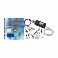
KIT UNDERSTANDING SIGNALS
Manufacturer
Parallax Inc
Datasheet
1.28119.pdf
(137 pages)
Specifications of 28119
Lead Free Status
Contains lead
Accessory Type
Oscilloscope
Interface Type
USB
For Use With/related Products
BASIC Stamp® 2 and Board of Education
Lead Free Status / Rohs Status
Lead free / RoHS Compliant
Available stocks
Company
Part Number
Manufacturer
Quantity
Price
Company:

Part Number:
281197-2
Manufacturer:
TE
Quantity:
20 000
Company:
Part Number:
281197-2
Manufacturer:
MOLEX
Quantity:
2 500


Chapter 7: Pulse Width Modulation with Infrared · Page 81
Chapter 7: Pulse Width Modulation with Infrared
Have you ever wondered how the remote for your TV or VCR works? Infrared is what
keeps you on the couch! When you press the power button on your remote control, a
unique series of infrared energy bursts are emitted from the remote and radiate into the
room. An infrared (IR) detector inside your TV decodes the signal and switches on your
TV.
IR detectors are “tuned” for a specific frequency. The detector included the
Understanding Signals kit is tuned for 38.5 kHz. The detector has a band pass filter that
limits the input to 38.5 kHz only. This means that the IR detector will give an output
only when a 38.5 kHz signal is received. The detector ignores all other inputs signals.
Data is transmitted by modulating the 38.5 kHz signal. This is done by varying the
amount of time the 38.5 kHz signal is on and off. This works something like the
asynchronous data signal that was covered in Chapter 6. Asynchronous communications
use “high” and “low” signals at specific times to send data. The only difference in the IR
protocol is that it uses a 38.5 kHz signal instead of the “high” signal. The times of the
38.5 kHz and the “low” are still controlled at specific times like the asynchronous signals
we all know and love. The only other difference is that it is not the state that determines
whether a bit is a one or a zero, but the duration of the bit determines its state.
The detector’s output is active-low. That means that the output is low when a 38.5 kHz
IR signal is being received. Conversely, when there is no 40 kHz signal, the detector’s
output is high. Figure 7-1 depicts the data bit stream from a Sony remote control. The
receiver counts how long the signal is low. If it is 1.2 ms then that bit is a logic 1; if the
signal is low for only 0.6 ms then it is a logic 0.
Figure 7-1: Infrared signal pulse example
Related parts for 28119
Image
Part Number
Description
Manufacturer
Datasheet
Request
R


Part Number:
Description:
Microcontroller Modules & Accessories DISCONTINUED BY PARALLAX
Manufacturer:
Parallax Inc

Part Number:
Description:
BOOK UNDERSTANDING SIGNALS
Manufacturer:
Parallax Inc
Datasheet:


Part Number:
Description:
COMPETITION RING FOR SUMOBOT
Manufacturer:
Parallax Inc
Datasheet:


Part Number:
Description:
TEXT INFRARED REMOTE FOR BOE-BOT
Manufacturer:
Parallax Inc
Datasheet:
Part Number:
Description:
BOARD EXPERIMENT+LCD NX-1000
Manufacturer:
Parallax Inc
Datasheet:

Part Number:
Description:
CONTROLLER 16SERVO MOTOR CONTROL
Manufacturer:
Parallax Inc
Datasheet:

Part Number:
Description:
BASIC STAMP LOGIC ANALYZER
Manufacturer:
Parallax Inc
Datasheet:

Part Number:
Description:
IC MCU 2K FLASH 50MHZ SO-18
Manufacturer:
Parallax Inc
Datasheet: