28119 Parallax Inc, 28119 Datasheet - Page 73
28119
Manufacturer Part Number
28119
Description
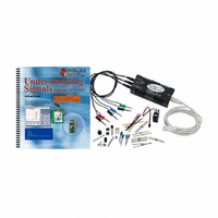
KIT UNDERSTANDING SIGNALS
Manufacturer
Parallax Inc
Datasheet
1.28119.pdf
(137 pages)
Specifications of 28119
Lead Free Status
Contains lead
Accessory Type
Oscilloscope
Interface Type
USB
For Use With/related Products
BASIC Stamp® 2 and Board of Education
Lead Free Status / Rohs Status
Lead free / RoHS Compliant
Available stocks
Company
Part Number
Manufacturer
Quantity
Price
Company:

Part Number:
281197-2
Manufacturer:
TE
Quantity:
20 000
Company:
Part Number:
281197-2
Manufacturer:
MOLEX
Quantity:
2 500


Chapter 5: Synchronous Serial Communication
Data can be transmitted in either of two fashions: parallel or serial. Between the two,
parallel data transmission is the fastest method, but it requires many I/O lines. Serial data
transmission generally requires 1, 2, or 3 I/O lines. There are two prevalent modes of
serial communications: synchronous and asynchronous. Synchronous is a word that
means “with a clock”, whereas asynchronous is a word that means “without a clock”.
This chapter introduces synchronous data communications.
Since many, many devices (i.e. chips) available today are accessed via a synchronous
serial interface, it is essential to be able to “talk” to these devices with ease. In this
chapter, a BASIC Stamp will be used to configure and read an A/D converter. With the
help of the OPTAscope, these signals will be captured, studied, and understood. This
level of understanding of synchronous data transfer will arm you with the knowledge and
vocabularies you need to read a chip’s datasheet, and write a program to interface with it.
ACTIVITY #1: CAPTURING SYNCHRONOUS SERIAL COMMUNICATION
In this activity we will build an A/D converter circuit with an ADC0831 and capture the
clock and data signals to see exactly how data is transmitted between the A/D converter
and a BASIC Stamp. As the potentiometer’s tap knob is turned, you will see the 8-bit
value sent from the ADC0831 change.
Parts Required
(1) ADC0831 8-bit A/D converter
(1) 10 kΩ potentiometer
(14) Jumper wires
Building the Example ADC0831 Circuit
√
√
Build the circuit shown in Figure 5-1 and Figure 5-2. It is the same for the Board
of Education and HomeWork Board.
Carefully connect the CH1 probe to pin 6 of the ADC0831, the CH2 probe to pin
7 of the ADC0831, and a Ground probe to Vss, as shown in Figure 5-2.
ADC0831 specifications and applications can be found on the datasheet, available online
at http://www.national.com/pf/AD/ADC0831.html.
Related parts for 28119
Image
Part Number
Description
Manufacturer
Datasheet
Request
R


Part Number:
Description:
Microcontroller Modules & Accessories DISCONTINUED BY PARALLAX
Manufacturer:
Parallax Inc

Part Number:
Description:
BOOK UNDERSTANDING SIGNALS
Manufacturer:
Parallax Inc
Datasheet:


Part Number:
Description:
COMPETITION RING FOR SUMOBOT
Manufacturer:
Parallax Inc
Datasheet:


Part Number:
Description:
TEXT INFRARED REMOTE FOR BOE-BOT
Manufacturer:
Parallax Inc
Datasheet:
Part Number:
Description:
BOARD EXPERIMENT+LCD NX-1000
Manufacturer:
Parallax Inc
Datasheet:

Part Number:
Description:
CONTROLLER 16SERVO MOTOR CONTROL
Manufacturer:
Parallax Inc
Datasheet:

Part Number:
Description:
BASIC STAMP LOGIC ANALYZER
Manufacturer:
Parallax Inc
Datasheet:

Part Number:
Description:
IC MCU 2K FLASH 50MHZ SO-18
Manufacturer:
Parallax Inc
Datasheet: